The rated fatigue pressure of components is a fundamental consideration in fluid-power system design. It’s uniquely important in hydraulics because an internal pressure wave transmits through the circuit each time the load is engaged.
In applications with short cycle times, such as injection molding, die-casting, and rock breaking, the pressure envelope can be energized hundreds of times per day. High-pressure cyclic loading can lead to the initiation of microscopic cracks. If the cracks propagate and link together, fatigue or failure of the component may occur. In applications where the system’s dynamic load is unpredictable, such as in mobile, off-highway, and construction equipment, high-pressure excursions, or spikes, also occur. If the pressure spike is sufficiently high, a single event can cause fittings, tubes, hoses, or valves to burst. In either case, exceeding the pressure rating of components can result in fluid loss, component failure, and machine downtime.
The fluid-power industry uses accelerated test methods for validating the internal rated fatigue pressure (RFP) of components. The RFP represents the maximum pressure that a component is verified to sustain with a known probability for the rated life without failure. Several common methods for fatigue pressure-rating components are listed (see the table in “Standardized test methods").
Three basic criteria are used to verify the pressure rating of fluid-power components:
• Proof and leakage
• Single-cycle burst
• Cyclic endurance
Proof pressure and leakage tests are designed to prove the fabrication integrity of test specimens. The safety factor in a proof test is typically “2 times.” Thus, a component rated to 5,000 psi must pass a 10,000-psi proof test.
In the SAE J343 proof test, hose assemblies are hydrostatically tested to the specified proof pressure for at least 30 seconds and not more than one minute. The specimen must not show any evidence of failure or leakage. SAE J343 also includes a two-cycle hydrostatic leakage test at 70% of the specified minimum burst pressure. The duration of the test is 5.0 to 5.5 minutes. As in the proof test, the specimens must not leak.
A proof test requires an intensifier with proportional control, plus high-pressure tubes, fittings, and sensors. To observe leaks, the component must be filled with liquid and placed in a transparent enclosure. If the specimen passes a proof test, it may be evaluated in a single-cycle burst test.
Burst tests are designed to simulate a single high-pressure excursion within a component. The typical safety factor is “4 times.” Thus, a component rated to 5,000 psi must have an average burst pressure exceeding 20,000 psi. NFPA T6.1 specifies the evaluation of five specimens; therefore, the standard deviation of the mean burst pressure can be factored into the burst rating.
A single-cycle burst test gradually increases the internal pressure of a component up to a magnitude that’s sufficiently high to cause failure. Because this is a static pressure test, it’s important that the rate of pressure rise be limited to 1% per second of the estimated burst pressure. Useful tools for safely conducting a burst test include a concrete enclosure with a heavy steel-plate cover, an air-over-water intensifier with proportional control, plus high-pressure tubes, fittings, and sensors. The component under test must be filled with liquid to limit the amount of energy released when it bursts. As one might imagine, spill containment is necessary.
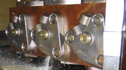
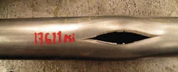
The various photos in the article show results from several successful burst tests. Test specimens must be discarded after high-pressure burst testing because component integrity has been compromised.
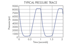
Cyclic endurance tests simulate the repetitive pressure-loading encountered in fluid-power systems. The cyclic test pressure (CTP) is typically 1.25 to 1.33 times higher than RFP. Thus, a component that has a 5,000 psi RFP will typically be evaluated at a CTP of 6,250 to 6,650 psi. Hydraulic hoses are subjected to the cyclic fatigue pressure a minimum of 100,000 times. Typically, metal components used in hydraulic equipment have a million-cycle life rating. Shown in the “Typical pressure trace” figure is a plot of fluid pressure resulting from cycle endurance testing.
Pressure-wave evolution, overshoot, plateau pressure, pulse duration, and decay times are specified within standard test procedures to reduce test variability. The duration of each pressure-cycle is typically less than two seconds. Maximum pressure-rise rate can reach as high as 80,000 psi per second.
Large components, such as cylinders, require very high instantaneous flow rates generate the desired pressure-rise rate due to fluid and system capacitance. If the system can generate a sufficient flow, it’s possible to concurrently test multiple samples. Four hose specimens are required to conduct a cyclic endurance test per SAE J343. In NFPA T2.6.1, the number of test specimens required to verify the rated fatigue pressure depends on the material of construction, CTP, design assurance, and confidence levels.
Engineers routinely evaluate fatigue pressure ratings to validate new suppliers, designs, and materials. In the following examples, endurance tests were used to diagnose field problems and enhance product reliability.
Filter housings that were failing at 5,000 psi in the field were evaluated per NFPA T2.6.1. The failures transpired in the root of the thread on the bowl. After redesigning the area where the failure occurred, the filter housing was retested with no failures in the lab or the field.
Sectional spool valves were failing in the field at 5,000 psi. The failure took place in the casting between the work ports. After redesigning the area where the failure occurred, the valve section was retested with no failures in the lab or the field.
Hydraulic hoses were failing in the refuse hauling fleet of a national contract waste-disposal company within one year of service. After evaluating the fatigue ratings of hoses from several manufacturers, the fleet converted to more durable hoses and subsequently experienced much lower oil consumption and maintenance costs.
THOMAS S. WANKE is the Director of the Fluid Power Institute at the Milwaukee School of Engineering. He may be reached at (414)277-7191 or [email protected].


