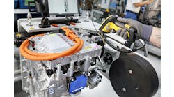
The objective of flushing a hydraulic system is to eliminate sludge, varnish, debris and contaminated or degraded fluid from conductor walls and other internal surfaces and system dead spots. Reasons for performing a system flush include:
1. Fluid degradation - resulting in sludge, varnish or microbial deposits.
2. Major failure - combined with filter overload disperses debris throughout the system.
3. New or overhauled equipment - to purge 'built-in' debris.
In a perfect world, if we needed to perform a system flush, we'd have a power flushing rig available to us. Power flushing involves connecting the system to a purpose-built hydraulic power unit to circulate a low viscosity fluid at high velocities to create turbulent flow conditions (Reynolds number > 2000).
The flushing rig is typically equipped with a pump that has a flow rate several times that of system's normal flow, directional valves, accumulators, fluid heater and chiller and of course, a bank of filters.
The directional valves enable the flushing direction to be changed, the accumulators enable pulsating flow conditions and the heater and chiller enable the temperature of the flushing fluid to be increased or decreased, all of which can assist in the dislodgment of contaminants from conductor walls and circuit dead spots.
Analysis of the flushing fluid is performed regularly during the power flushing operation to determine the point at which the system has been satisfactorily cleaned.
However, in the real world, there are lots of situations where this equipment is not available to us, or it doesn't make economic sense to hire and use it. This leaves the double oil and filter change - usually performed in combination with mechanical cleaning.
A double oil and filter change involves an initial oil drain and filter change, which expels a large percentage of contaminants and degraded fluid. The system is then filled to the minimum level required and the fluid circulated until operating temperature is reached and the fluid has been turned over at least five times. The oil is then drained and the filters changed a second time. Ideally, an appropriate oil analysis test should be performed to determine the success of the flush.
To maximize the effectiveness of this technique, the system should be drained as thoroughly as possible and the reservoir completely drained and mechanically (manually) cleaned.
Keep in mind too, that with the exception of new or overhauled equipment, the need to flush a hydraulic system generally represents a failure of maintenance. This is something you want to avoid. With this in mind, a good place to start is my special report, "6 Costly Mistakes Most Hydraulics Users Make... And How You Can Avoid Them", available for free download here.
Continue Reading
Continue Reading
Hydraulic System Flushing Procedures
Dec. 20, 2019
Intensification circuit uses rotary flow divider
June 5, 2006
Sponsored Recommendations
Sponsored Recommendations
How Variable Volume Pumps Work
Feb. 6, 2024
What is a Check Valve and How Does it Work?
Feb. 6, 2024
