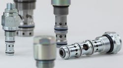
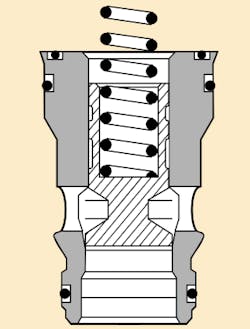
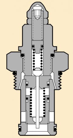
Valve cartridges can be thought of as "bodyless" - valves without an integral housing - because they consist of only the internal moving elements of the valves. After a cartridge is inserted into a cavity, such as a manifold with appropriate flow passageways, the resulting valve performs like any conventional valve. Slip-in cartridges are held in the cavity by a cover plate, Figure 1; screw-in-type cartridges mate with threads in the cavity, Figure 2. Another type of insertable cartridge has circumferential grooves. After it is inserted into the cavity, it is held in place by swaging internally with a tapered pin that expands the cartridge diameter into interference contact with the bore.
Versatility
A wide variety of cartridges allows engineers to find almost any hydraulic control function in cartridge form - with very few limitations. Here are the control functions readily available in cartridge configuration today:
- relief valves
- sequence valves
- pressure-reducing valves
- check valves
- pilot-operated check valves
- load-control valves
- counterbalance valves
- flow-control valves (pressure- and non-pressure-compensated, fixed, priority, proportional divider)
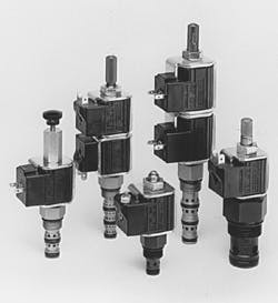
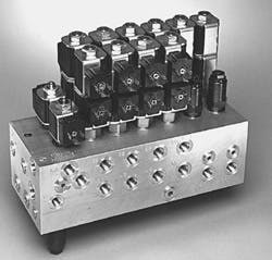
- solenoid valves in 2- or 3-way poppet or spool type, and 4-way, 2- or 3-position versions, Figure 3
- electro-proportional directional, flow, and pressure controls, and
- specialty valves — such as shuttle valves and velocity fuses.
One innovation in cartridge valve technology today is the incorporation of two or more functions into a single cartridge housing — for example, check valves with flow-control valves, dual crossover reliefs, etc.
Custom valve packages
A manifold with at least one cartridge valve - but more commonly with two or more — may be thought of as a valve package. Often, the manifold is custom designed for a specific application or function. The valve package may contain some or all of the control valves for a hydraulic system. Custom-designed valve packages offer many advantages in mobile and industrial equipment.
A custom valve package can be:
- a single cartridge installed in a manifold that has been designed to fit a specific mounting configuration, or
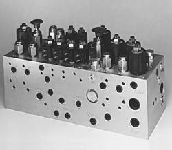
- a manifold containing multiple cartridge valves performing some or all functions in a complete hydraulic control system, Figure 4.
System advantages
The cartridge-design approach can offer important advantages over systems plumbed with individual components:
1. Light weight and compact size. Combining several functions into a single manifold may save valuable space and weight, often occupying only 10% to 20% as much volume as conventional line-mounted systems plumbed with fittings, hose, and tubing. This space and weight reduction may provide substantial energy savings, particularly in mobile applications.
2. Economical. On many systems, the cost of a custom valve package — if built in sufficient quantities — can be equal to (or less than) that of a system with individually plumbed components. This premise is especially valid if one compares the total installed cost, considering all components and labor.
3. Leakage resistant. Because a valve package eliminates so many connections, system leakage potential is reduced drastically. In addition to fewer connections and potential leakage sources, custom valve packages reduce the amount of attached conventional plumbing that may work loose from machine vibration.
4. Efficient. Valve packages that eliminate interconnecting lines and fittings lead to higher overall system efficiencies. Not only is pressure drop through lines and piping reduced, but higher energy efficiency can be achieved for a machine. Many times, a valve package can be mounted directly on an actuator or pump, where it will be most effective in performing its functions. The close proximity of valve and actuator also will minimize system compliance for those systems - such as aircraft flight controls —- where the position of a controlled surface is critical.
5. Convenient. A factor important to OEMs: the valve package that they receive from their supplier is normally already fully assembled and pre-tested. They simply mount the package on their machine, connect it, and the system is ready to run. Being more compact, valve packages sometimes can be mounted where they are less susceptible to external damage.
6. Easily serviced. Machines not only must be reliable, but also should be easy to service and maintain. This is an important characteristic of valve packages because troubleshooting and servicing may be a simple procedure. Cartridges usually can be removed and replaced quickly without disturbing any external plumbing.
7. Neat. Finally, eliminating piping, fittings, etc. normally leads to a better-looking machine. A clean design will not affect performance, but a good-looking machine on the dealer's sales floor in a competitive market can be an advantage to the OEM.
Logic circuits
The advent of hydraulic logic elements (basically 2-way, slip-in poppet cartridges), that are controlled with low-flow pilot signals, has expanded the horizons for valve packages. These compact, cost-effective elements can handle flows from 5 to more than 5,000 gpm, at pressures to 6,000 psi or higher.
Individual logic elements can be arranged so that trapped fluid pressure is relieved before full connection to a tank line. Also, logic elements can be actuated at optimum points in the system's cycle — much as a spark plug must fire just before top dead center in a gasoline engine for optimum performance.
Disappearing disadvantages
In the past, producers of cartridge components expanded their product lines by adding proprietary items. Cavities were developed randomly; manufacturer-to-manufacturer interchange was rare. Today, however, a series of industry-common cavities have evolved through competitive pressure — to the extent that now several sources typically can compete on a fit/installation basis. In addition, an NFPA/ISO effort is in process to develop a world standard for cartridge cavities. There are two proposed standards, inch and metric. These proposed standards are already being implemented by some cartridge makers. Also, cartridge product lines continue to proliferate so that choices of hardware are available for most function requirements.
In addition, the viability of complex manifolds has grown. Building manifolds for more than six or eight cartridges once was considered risky because of potentially high scrap costs due to machining mistakes, and cleaning and deburring often were difficult. Now, CAD capability and CNC machines greatly reduce concerns about fabrication by minimizing operator errors. These techniques also shorten the product-development cycle. New thermal, ultrasonic, and chemical deburring techniques simplify manifold clean-up. As a result, manifolds with 20 or more cartridge cavities, Figure 5, are no longer unusual.
