Pneumatics, the technology that harnesses the power of compressed gases, touches everyone’s life daily. 18% of all industrial energy is used to compress air and gases, according to the DoE. It is critical for making cement and flour, as well as blow-molding plastic bottles.
Pneumatics present several advantages: It is the least expensive transmission medium—air, or in some cases, separated or inert gases; it also has lower installation costs generally. But air pressure is typically below 250 psi, making it hard to detect and control leaks. It is also less efficient than hydraulics at transmitting fluid power.
Pneumatics powers a wide range of tools and equipment, in many instances replacing the electric power cord with an air hose. Since pneumatic power is intrinsically safe, a number of industries could not operate without it.
At the heart of all pneumatic systems is a compressor that turns the air or gas into kinetic fluid power.
Compressor Basics
Compressors turn gases into power. There are two main categories of air compressors:
Dynamic. These compressors raise air pressure by converting air velocity into pressure (centrifugal).
Positive displacement. These compressors trap a charge of air and physically shrink the space to increase pressure (sliding vane, rotary screw, reciprocating, rotary lobe).
There are also many types of compressors:
Centrifugal. Use low-pressure, high-volume air flow and no oil is added to the air (dynamic).
Different types of air compressors require lubricants with suitable ISO viscosities and additive packages. The lubricant usually depends on the compressor’s load, environment, temperature, and speed parameters.
Centrifugal Compressors
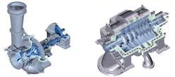
Centrifugal compressors, also called radial compressors, increase air pressure by radially accelerating air flow and then pressing it against the compressor body. They are well-suited for continuous duty compressing large volumes of gas/air. They provide oil-free air and create higher airflows than similarly sized positive-displacement compressors. Centrifugal compressors can be a simple single stage for lower pressure or a more complex multi-stage design that supplies higher pressures.
Only the rotating shaft bearings and drive gears are lubricated, so the airflow is not exposed to oil. Lubricant viscosity varies between ISO 22 and 68, depending on shaft speed and bearing load. The oil must be compatible with the rotating shaft seals so no oil moves into the airflow area. The drive design of centrifugal compressors determines if anti-wear additives are needed or rust and oxidation additives for direct-driven journal bearings.
Sliding Vane Compressors
Sliding vane compressors have many advantages. They are light in weight, compact, operate quietly with minimal vibrations, have few parts and discharge the coolest possible air.
Sliding vane compressors are lubricated at the shaft bearings, vane slots, vane tips and chamber surfaces. The vane slots and tips, as well as the interior of the cylindrical compressor chamber, are oil-lubricated; thus, these compressors supply an air and oil mixture.
If the air needs to be oil-free, the supplied air must then go through a downstream air-oil separator. Separators use a filter to force the oil mist into larger droplets for easier separation and return to the compressor’s oil supply.
Vane compressor oil viscosity is determined by operating temperature and speed. The need for anti-wear additives in the oil is typically determined by the load.
Oil is injected into the air stream to lubricate the seal between the vanes/rotor and cylinder (housing), the bearings, the vanes and cylinder surfaces.
Vane compressors are generally limited to applications well below 100 hp because of the bending stresses placed on the vanes. ISO 68 and 100 oils are the most common viscosity grades. Users should always reference the OEM manual for correct viscosity and recommendation for either anti-wear (AW) or rust and oxidation (R&O) oils.
Rotary Screw Compressors
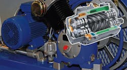
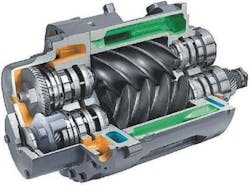
Within the last 60 years, oil-injected screw compressors have become the most popular type of compressor in the world. It works by trapping a volume of air at the intake area between two counter-rotating screws and reducing its volume as the screws move it toward the discharge outlet. A film of lubricating and cooling oil on the screw’s surfaces seals air in the confines of the screws to prevent leaks. Some tolerances are so tight that oil films are unnecessary.
Several lubrication concerns must be addressed to ensure screw compressors operate reliability:
- Oxidation-stable lubricants must be used to prevent varnish building up on the screw. The varnish reduces the clearance and greatly increases the operating temperature, leading to even more varnish production and eventual compressor failure.
- Intake air and oil must be clean to stop particulates from damaging the screw surfaces.
- Oil foaming reduces compressor efficiency as it cannot adequately seal the screw surfaces.
- The oil must have good demulsibility to prevent emulsions from interfering with oil removal in the air-oil separator. (Demulsibility is a measure of an oil’s ability to release water.)
Rotary screw compressors are typically lubricated with ISO 46 or 68 anti-wear oils. Synthetic lubricants are gaining wide acceptance for controlling varnish deposits.
Rotary Lobe Compressors
These compressors consist of two symmetrical lobe rotors mounted on separate shafts in parallel, which rotate in opposite directions to each other at high speeds. Timing gears synchronize the lobes’ rotation to maintain constant clearance between the two. The compressors are efficient at producing significant air flow.
Rotors can be up to eight feet long and three feet wide, or small enough to pick up and carry around in a lunchbox.
Non-contacting rotary lobe blowers belong to the group of dry-running positive-displacement compressors. This means there is no need for oil in the compression chamber. Only gearbox and bearings, which are separated from the pumping chamber, are oil-lubricated.
These compressors have low compression ratios with pressures up to 25 psi and high capacities up to 30,000 cfm.
Rotary lobe blowers/compressors tend to run hot (with exhaust air up to 350°F). Therefore, lubricant viscosity is usually an ISO 150 or 220 to handle the temperature thinning of the oil film in the gearbox. Synthetic oils are common to handle the high temperature and better resist oxidation.
At the gear end, timing gear teeth are lubricated by being partially submerged in non-extreme-pressure (EP) or anti-wear oil. The gear teeth also sling oil on the gear-end bearings. At the drive end (or belt side), bearings are typically grease-lubricated. Users should always check OEM specifications for correct fluid and/or grease specifications.
Reciprocating Compressors
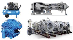
Reciprocating compressors are based on the same principles as internal combustion engines (pistons, rings, cylinders and valves). The difference is the goal is gas compression instead of combustion at the top of the piston.
Reciprocating compressors are typically used for their high compression ratios (ratio of discharge to suction pressures) without high flow rates, and the process air/gas is relatively dry.
A reciprocating compressor uses the piston movement inside a cylinder to compress air. As the piston moves downward, the exhaust valve closes and a vacuum is created inside the cylinder, forcing the intake valve to open and suck air into the cylinder. As the piston rises, the intake valve closes, and compressed air leaves the cylinder through the exhaust valve.
Lubrication is typically handled by splash lubrication or a pressured central subsystem. Large piston compressors have direct-injected or drip-fed lubrication at the top of the piston-air valve area.
Small (up to 20 hp), air-cooled reciprocating compressors are usually lubricated with SAE 30 engine oil or ISO 68 to 100 R&O or anti-wear oils; 50 hp and greater reciprocating compressors typically have two separate lubricating subsystems: drip-feed a non-carbonizing ISO 100 or 150 synthetic ester or diester lubricant for the compressor head’s reed valves, and SAE 30 or 40 engine oil or ISO 100 or 150 anti-wear in the crankcase.
For large, horizontal crosshead piston compressors, the choice of cylinder oils depends on the solvency of the gas and how much it prevents the lube from being washed off cylinder liners. Esters and diesters have replaced the compounded oils containing animal fats or vegetable oils—natural esters—that were first used years ago.
Compressor Lubricants
The most important property of a compressor lubricant is its viscosity. It must be matched to the compressor’s load, environment, temperature, speed and its components. Considerations include:
Load. Input horsepower and delivered psi of the gas, single-stage versus multi-stage compression.
Environment. Type and reactivity of gas being compressed, cleanliness of gas for filtration, humidity.
Temperature. Ambient and operating temperature of compressor, and temperature of the compressed gas.
Speed. RPM of the rotating components.
Lubricant should have some of these qualities:
- A stable base oil that resists oxidation but reacts with other compressing gases to prevent deposits and extend or maintain oil life.
- Good demulsibility to handle humidity and prevent oil/water emulsions in the air-oil separator.
- Anti-corrosion protection to handle rust as well as any gas-induced corrosion.
- Non-foaming to provide a proper seal between rotating screws and vane and sliding pistons. Foaming also causes major problems in downstream air-oil separators.
- Balanced and compatible with additive package for compressor and the type of gas being compressed.
Users should follow these six simple rules during and after fluid changes to extend the compressor’s life.
- Analyze oil before changing it out.
- If changing brand/type of fluid, get information on the current and new lubricants. Many compressor lubricants are not compatible with each other or with certain seal materials.
- Flush system using approved blending agent and procedures.
- Check sight glass daily for foaming tendencies.
- Take and analyze sample a week after changing fluids.
- Do a quarterly oil analysis/particulate count.
Compressor efficiency and operating life are directly affected by the lubricant used on it, it is only logical to conduct routine oil analysis, including particle count, of the compressor fluid to prevent failure.
Because of the high oxidative environment as well as moisture and high temperatures, an oil analysis program is recommended for any compressor critical for plant operations. Oil analysis programs allows changing fluids at the best time and assists in identifying equipment concerns before they become serious.
By their nature, air compressors take in airborne contaminants every second they operate. Contaminated lubricants hurt compressed air quality more than anything else. Just compressing atmospheric air to 125 psi creates an 800% increase in the concentration of contaminants.
The biggest problem on the maintenance side is air filtration. Users must keep the incoming air stream clean. Otherwise pneumatic tools wear out more quickly. Pulling air from hot, moist and dirty environments makes it more difficult to reduce operating expenses.
John Cummins is vice president of product technology and an investing partner of Hydrotex. This article is based on material he delivered in a webinar presented by the Society of Tribologists and Lubrication Engineers, an international professional not-for-profit society based in Park Ridge, Ill. Jeanna Van Renesslar is a freelance writer based in the Chicago area.
This article is part of Power & Motion's Fundamentals of Fluid Power: Pneumatics ebook; download the full guide to learn about the latest technologies and design methods for developing modern pneumatic systems.
