Some hydraulic applications require coordinating the motion of two or more actuators. A common example is moving two or more actuators at the same time, at the same speed and to the same position. There are a couple of ways in which this can be approached.
In the past, it was common to gear one actuator to another with one of them being the master. The other actuator(s) would try to follow the master’s actual position.
There are a couple of problems with this. It is difficult to calculate the master’s velocity due to noise and feedback resolution. Also, if a slave cannot keep up, there must be some way to slow the master. Finally, slave actuators always lag the master. A better approach is to generate the same virtual master for each axis. If there are following errors, they should be the same for all the actuators. Then the virtual master for all slaves can be slowed down.
Nowadays, modern motion controllers generate a target motion profile for each actuator it controls. The target motion profile includes the target position, velocity and acceleration. Sometimes the target jerk or derivative of acceleration is also calculated.
The advantage of following a target or virtual master is that the virtual master is noise-free, so it can generate the same target velocities and accelerations for all the slaves. The slaves can then use this information to generate velocity and acceleration feed forwards. This greatly reduces following errors.
Feed forwards estimate or predict the control output needed by the actuator to move at any target velocity and acceleration. If this estimate is within 5% of the actual value, the PID only needs to correct for 5% of the error instead all of it.
Generating a target position, velocity and acceleration for all the slaves lets operators generate different motion profiles for all actuators and execute them as a function of time. Sometimes actuators must move to different positions while going different distances and velocities but still arrive at the same time. This is easily done by setting the actuator that needs to move the farthest as the master actuator.
Next, for each slave actuator, find the ratio of that slave’s distance to the master’s distance and multiply the master’s speed, acceleration and deceleration by that ratio to get the slave’s speed, acceleration, and deceleration. So, if a slave needs to move half the master’s distance, the slave’s target speed, acceleration and deceleration will be half the master’s target speed, acceleration and deceleration.
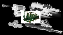
An example of this is a sawmill headrig application. Logs are not perfect cylinders; they are slightly tapered or conical. To get the most usable wood from a log, the headrig’s knees need to move different distances to get the log into the best position for cutting. But it is important that all the knees move synchronously and to their final position at the same time, so they don’t bend the log.
There are applications where actuators move using independent functions as a function of time. An X and Y actuator could cut a pattern out of a piece of material. So, each actuator then needs to execute its motion profile as a function of time. If an X and Y actuator were to execute the same function, they would just move back and forth in a straight line. This is not helpful; the X and Y motion profiles must be different.
One way of doing this is to use cam tables or cubic splines. Cam tables let operators indicate a set of positions as a function of a set of times. Each actuator can have its own set of positions, but they should share the same set of times. This ensures the X and Y actuator can be at designated x,y coordinates at a designated time. This technique can be expanded to more than two actuators if required.
The most sophisticated version of this occurs when several actuators use cam tables/cubic splines executed as a function of an external master or encoder. An example of this from the sawmill industry involves the feed chain that moves logs through chipper heads and saws. In this case, an encoder attached to the feed chain computes the chain’s speed.
When a log breaks a photo-eye, the encoder resets to 0. The encoder’s counts, or position, are used to index each actuator’s cam table/cubic spine to its position. The advantage of this is that if the chain changes speed, all the geared actuators change speed accordingly. This requires some complicated math, but it is done inside the motion controller.
In practice, the cam tables’ set of positions is downloaded while the previous log is being cut. Each log is different, so a different set of positions is always being downloaded for each log.
The difficulty with this method is that the actuators are now geared to the feed chain encoder. It is easy to read the counts and scale that to position. However, it is harder to compute an accurate velocity when there is a lot of jitter in the feed chain encoder as each link in the chain goes over a sprocket. This makes calculating the feed chain velocity and acceleration difficult, but it is needed for using the feed forward gains.
The feed chain should run at a constant speed, so the acceleration calculation may not be important. But the chain’s velocity is important because it is used to compute the slave actuators’ target velocities. If an accurate target velocity and acceleration can be computed for the slave actuators, they can be used to calculate feed forwards and improve tracking. Filtering can reduce the encoder noise due to the sprockets and improve estimates of velocity.
In general, engineers should not gear to the feedback of an actuator that isn’t controlled by the motion controller. If the motion controller controls the actuator, the target position, velocity and acceleration should be used rather than the feedback or actual position, velocity and acceleration. Always try to follow a computer-generated target position, velocity and acceleration because these are usually high-precision, floating-point values rather than noisy and quantized positions.
Peter Nachtwey is president of Delta Computer Systems Inc., Battle Ground, Wash. For more information, visit deltamotion.com.

