Materials such as paper, plastic film, foil, and cloth often are produced in long, continuous sheets that are rolled up for more-convenient handling and transportation. These rolls of material vary significantly in size and weight—ranging from 2- to 200-in. wide and weighing as much as several tons.
The Converting Industry takes these continuous rolls of thin, flat materials—known as webs—threads them though processing machines (such as printing presses, laminators, coaters, slitters, etc.), and changes the web of material into an intermediate form or final product. For example, a converter’s equipment might take a web of plastic film, cut it into lengths, and fuse their edges, thus converting it into plastic bags. This activity is known as web processing.
Keeping the Web on Track
A moving web of material has a tendency to tend to track off course and wander out of alignment during converting processes for any of several reasons. When a web is out of alignment with the equipment processing it, the quality of the finished product may suffer, and scrap rates can escalate. To avoid these problems, designers have developed a variety of automatic web-guiding systems that ensures production accuracy and reduces waste.
Web-guiding systems typically are positioned just before a critical stage on a converting machine (for example, just before a print station on a printing press). Each type of web guiding system uses a sensor to monitor the web position for lateral tracking, and each has an actuator to shift the running web mechanically back on course whenever the sensor detects movement away from the set path. Actuators may be pneumatic or hydraulic cylinders, or some kind of electromechanical device.
Because the web may be fragile—particularly at its edge—non-contact sensors are used. These sensors may be pneumatic, photoelectric, ultrasonic, or infrared. The system’s controls must put the output signals from the sensors into a form that can drive the actuator.
Many controls today are electronic, typically using an amplifier to convert signals from the sensor, then commanding a special servomotor incorporating a lead or ball screw for guiding actuation. Some electromechanical guiding systems also utilize computers. Of course, controls also can be pneumatic.
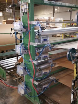
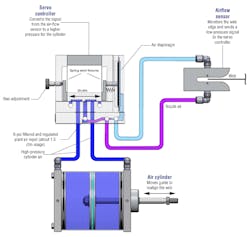
At Coast Controls, we manufacturer the world’s only proportional pneumatic web guiding system (Fig. 1). The machines use the same medium—compressed air—for sensing, controlling, and powering the actuating devices. The complete system consists of the All-Air servo controller, which processes signals from an airflow sensor to extend or retract a pneumatic cylinder on a guide assembly. We have used the same proportional controller on every system we have built since 1992, whether it is a displacement, steering, or shifting unwind/rewind guiding system. It is a time tested, proven design to say the least.
1. This machine handles up to four layers of laminated paper for making pet food bags. Here, three layers are brought together for subsequent gluing, folding, and cutting. The machine uses four all-pneumatic web-guiding systems that ensures that all high-speed webs remain in precise alignment.
These all-air systems are simple, cost-effective, and user-friendly. They require little operator training to install, set up, and run, and are easy to troubleshoot and maintain. In fact, they are pretty much maintenance-free, especially when compared to complex electromechanical guiding systems. Plus, they are inherently explosion-proof, which can be an important factor in the atmosphere of some converting operations.
Guide and Sensor
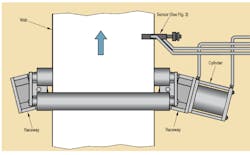
During a converting process, an air shaft is put through the center of a roll of material and positioned on a stand. The roll’s free end is then threaded through the processing machine and around the rollers on a downstream guide (Fig. 2). The guide’s raceways include linear ball bearings and a carrier block to provide load-bearing support, while allowing low-friction linear movement when the actuator strokes to correct any misalignment of the web.
2. The guide holds the moving web between two rollers; the actuator extends and retracts to position the carrier block.
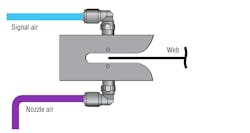
The air-flow sensor (Fig. 3), installed downstream from the guide, is the essence of simplicity. It consists of a sensor body with a slot for the edge of the web and opposing nozzles. Low-pressure air from the servo controller flows constantly into the nozzle at the bottom. Depending on the web’s position in the slot, it creates different backpressures at the opposing upper nozzle and, consequently, at the servo controller. To prevent dust or other foreign matter from clogging the air-flow sensor, the system provides for a continuous positive air bleed from both the opposed nozzle and signal orifices.
3. Cross-sectional view of simple, self-cleaning, non-contact sensor that straddles edge of web. Correctly positioned web partially blocks air flow between nozzles to establish neutral signal pressure.
Pneumatic Servo Controller
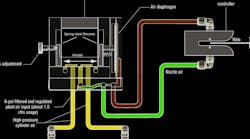
The All-Air servo controller (Fig. 4), is based on a friction-free design incorporating a moving shuttle suspended by two spring-steel flexures. These flexures position the shuttle to maintain a 0.002-in. clearance between it and the port plate underneath it. This configuration allows for almost-effortless shuttle movement and avoids any shuttle wear. Pressure signals from the air flow sensor impinge on the diaphragm at the right side of the controller. When the diaphragm develops enough force to compress the bias spring at the opposite end of the shuttle, the shuttle strokes and directs proportionally higher-pressure air to the proper end of the pneumatic cylinder. The cylinder’s stroke moves the guide to return the moving web of material to its proper position.
4. A diaphragm responds to the return signal from sensor and interacts with springs to position a shuttle within the servo controller to send a pressure signal to the appropriate end of cylinder that will correct web position.
The controller is adjusted so that the shuttle’s neutral position is established when the web edge partially blocks air flow between the two ports in the sensor. The system deadband width is between 0.003 to 0.005 in. at the air-flow sensor. When the web wanders to the left, exposing more of the upper nozzle, return pressure increases, and the diaphragm flexes more, pushing the shuttle to the left. Should the web drift to the right, it will block return flow completely, allowing the diaphragm to relax, and the bias spring pushes the shuttle to the right. The resulting proportional pressure signals to the cylinder automatically reposition the web until its position in the sensor brings the shuttle back to neutral. No action is required by the operator.
In effect, the air-flow sensor, All-Air servo controller, and pneumatic cylinder—along with the moving web of material—combine to form a closed-loop proportional control system. The servo controller converts and amplifies the return signal from the air-flow sensor to a higher pressure and sends the desired correction to the air cylinder. The cylinder then strokes to reposition the guiding assembly and accurately aligns the moving web.
Pneumatic Cylinders
There’s a lot of talk these days about the cost of compressed air, but our system consumes only about 1.5 cfm of plant air at 5 psi. Even at these low pressures, the cylinders generate enough force to position the low-friction components that support the guide. The air cylinder bores range from 3 to 8 in., depending on the application and the total weight of the load to be positioned.
A 3- to 5-in. bore cylinder is typically used for smaller intermediate guiding, whereas a 6- or 8-in. bore cylinder is normally used on larger intermediate guides or heavier unwind/rewind lateral shifting roll stands. The cylinder’s stroke is matched to the maximum linear correction the guide must make.
Adjustments and Installation
The all-pneumatic system is dependable and well suited to the production environment. It requires only three system adjustments—all of which are preset during pre-shipment testing at the factory. The first adjustment is the setting of the precision pressure regulator, which is furnished with each system, as is a pressure gauge and two-stage coalescing filter. The regulator is usually set at 6 psi. unless larger intermediate guides or heavier unwind-rewind stands are used.
The second adjustment is the gain control for sensitivity and reaction speed. This adjustment is set using a flathead screwdriver through an internal needle valve that establishes the nozzle pressure to the air-flow sensor. The final adjustment establishes the bias, which balances the shifting speeds and causing the piston rod to move at the same speed in each direction. Installation is simple: bolt the guide system in place and connect to plant air. Adjustments are rarely needed once the system has been installed.
Another advantage of the All-Air design is its simplicity. An operator’s learning curve is usually just a few minutes to understand. And because we use the same controller on every system we build, once you know how to operate one, you know how to operate any guiding system we manufacture. As a result, the system can be easily maintained by plant maintenance personnel without using complex training manuals, expensive spare parts, or electronic specialists for repairs.
Tom Marks is president of Coast Controls, Inc., Sarasota, Fla. For more information, visit the company's website or call (931) 355-7555.
