This file type includes high resolution graphics and schematics when applicable.
The compressed air delivered to a work point is often at a pressure higher than needed. Therefore, to maintain adequate machine force and torque—while reducing the amount of compressed air consumed—you should reduce the pressure supplied to the machine wherever you can. If done properly, this action will not compromise machine operation or speed, but it can lead to a big reduction in operating costs by reducing the load on your plant’s compressed air system.
Clamp-Press Circuit
Neglecting friction, the force or torque transmitted by a pneumatic system is directly proportional to the pressure applied to it—the higher the pressure, the greater the force. Regulators are widely used in pneumatic systems to limit the pressure delivered to a circuit or actuator, and a single regulator is used in many cases. However, a lower force requirement may exist for a portion of an operating cycle.
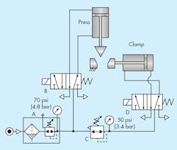
This scenario is illustrated in Fig. 1 by a clamp-press circuit. In this case, the clamping force is adjusted according to the nature and size of the part being clamped. Within the system, the main regulator of the filter-regulator unit (A) supplies a pressure of 70 psi to directional control valve (B), a 2-position, solenoid operated, spring return, 5-ported, 4-way valve. The main regulator also supplies 70-psi compressed air to a secondary regulator (C). The main regulator controls the force of the double-acting press cylinder.
The secondary regulator (C) downstream of the main regulator provides independent control of the clamping force. Compressed air from the secondary regulator is set to 50 psi and is connected to directional control valve (D). When the system operates, actuating the clamp cylinder directional valve causes the clamp cylinder to extend at whatever pressure is required to move the cylinder. Once it has fully extended to its clamping position, pressure in its base end rises to 50 psi. This limits the force generated by the clamp cylinder and saves energy by not transmitting higher pressure than is needed for clamping.
Differential Pressure Circuit
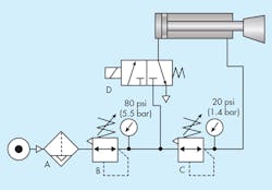
Energy is wasted when compressed air is used at pressures higher than required. In many applications, the pressure used for the non-work portion of a cycle (often, the return stroke of a cylinder) is the same as the work portion. Energy can be saved if the non-work pressure is less than the required work pressure. One method to reduce the amount of compressed air used in a circuit is the differential-pressure circuit (Fig. 2).
The circuit consists of an inline air filter with an automatic drain, two relieving type regulators (B and C), a double-acting cylinder, and a spring-return, 2-position, 3-way directional valve. Work is performed on the cylinder’s extension stroke, but low force is needed to retract the cylinder—thus, a low pressure.
The secondary regulator (C) is installed between the outlet of the primary regulator (B) and the rod-end port of the cylinder. The cylinder uses the lower pressure of 20 psi as an air spring to return the piston rod to its fully retracted position.
However, a potential problem exists with the extend portion of the cycle. Regulator (C) is a relieving type regulator, but if the rod-end pressure in the cylinder exceeds the 20 psi of the regulator, the cylinder will undergo slow extension and reduced force. Exhausting air from the rod-end would be forced to exhaust through the venting port of the secondary regulator (C). This problem is due, in part, to the secondary regulator being constantly supplied by the primary regulator at 80 psi. Reverse flow through the secondary regulator (C) is prevented.
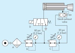
Figure 3 shows a circuit that accomplishes differential pressure and normal cylinder speed and force. By placing a quick-exhaust shuttle valve between the secondary regulator and the head-end port of the cylinder, pressure in the head-end will be exhausted through the quick exhaust rather than through the vent port of the regulator. During the retract stroke of the cylinder, the shuttle automatically shifts to block its exhaust port and direct the 20-psi air into the rod-end of the cylinder.
Dual-Pressure Circuit
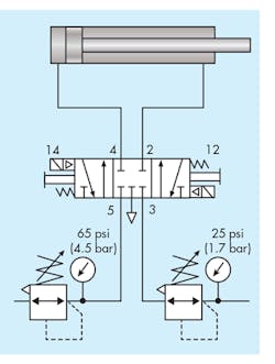
Another configuration for obtaining dual pressure is shown in Fig. 4. It operates on the same principle that many types of 5-ported, 4-way valves use with dual pressure supplies. Compressed air enters one end of the cylinder at high pressure, and the other end is supplied with air at a lower pressure. In essence, a double-acting cylinder extends at high pressure and retracts at low pressure. This is accomplished using a dual-pressure, 3-positon, 5-ported, 4-way, directional valve with a blocked center. In Fig. 4, the valve is supplied high pressure at port 5 and low pressure at port 3. The exhaust port is common to both.
When solenoid (14) is energized, pilot air pressure shifts the main valve spool to connect ports 5 and 4, causing the cylinder to extend at high pressure. De-energizing the solenoid (14) causes the opposite return spring to center the valve. Energizing solenoid (12) directs pilot pressure to shift the valve spool to connect ports 3 and 2, causing the cylinder to retract at low pressure. Dual-pressure circuits are known for their energy efficiency. Using high-pressure air only when needed reduces compressed air consumption and, hence, the energy to compress the air. These systems cycle thousands of times per day in most applications, and most machines use multiple circuits. Consequently, the lower energy use from multiple circuits and thousands of cycles quickly repays the initial cost; it continues providing lower operating costs for each application.
Torque Control of an Air Motor
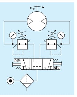
Sometimes an air motor requires variable torque capability. The magnitude of torque depends on the pressure at the motor inlet, whereas speed depends on the air flow. Figure 5 shows a motor circuit where the bidirectional motor torque can be different for clockwise and counter-clockwise rotation. Two secondary regulators are placed between the motor and the directional valve, which has a 5-ported body and 3-position, 4-way spool with blocked center. The secondary regulators must have reverse flow capability or check valves to bypass exhaust flow past each the regulator during reverse-flow conditions.
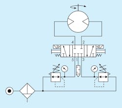
Reverse flow through regulators can be avoided with the circuit shown in Fig. 6. It consists of the same components, but now the secondary regulators are connected to the 5 and 3 ports of the directional valve. The same torque can still be accomplished by converting the directional valve into a dual-pressure supply valve.
What if a machine requires variable torque with the motor rotating clockwise, counter-clockwise, or both? This is where electropneumatic regulators provide versatility. Electropneumatic regulators provide variable output pressure, so motor torque can be matched to load demands. And depending on their sophistication, electropneumatic regulators can even follow a command signal, making them useful for continuous machine control.
Bill Service, Marketing Manager
Parker Hannifin Corp., Pneumatic Division
Intensifier Boosters Circuits
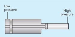
Sometimes the pressure needed for a particular part of a cycle exceeds that of the plant’s air supply. Examples of such conditions would be die cushion cylinders, test stands, and the like. If the volume of air needed is not large, a reciprocating booster may be the economical answer. Boosters may be of an air-to-air or air-to-oil type.
They also may be single or dual pressure. Single-pressure versions deliver compressed fluid from the intensifier. Dual-pressure types first deliver pressure from the main system to pressurize high-pressure fluid from the intensifier. No matter what type of intensifier is selected, certain guidelines should be followed.
Intensifiers generally operate faster when:
- Adequate input pressure exists.
- The ports and piping are not oversized. Consider the use of ports and connecting lines that reduce the volume necessary to compress.
- The intensifier-draining cylinder is pre-exhausted, and the high-pressure (driven) cylinder is at line pressure before the power stroke occurs.
- Bypass the intensifier with a pre-fill, low-pressure line by connected directly through a check valve to the pressure vessel and, similarly, to a dual-pressure intensifier.
- Regulate the driving pressure to the intensifier to achieve the required high-pressure output.
- Keep all piping lengths beyond the control valve to a minimum by having the tanks, intensifier, and pressure vessel as close together as possible.
- A single pressure intensifier usually provides faster cylinder action because it does not need to change from low to high pressure, but instead immediately supplies the high pressure.
- Intensifiers are generally used in circuits where limited quantities of high-pressure fluid are required.
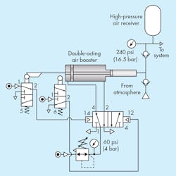
The illustration shows an air-to-air circuit of the single pressure type. This is a demand type of circuit, functioning only to bring the receiver pressure up to the desired pressure, which is controlled by regulator. Control valve (4) is the device that cycles the booster, controlled by the limit valves (5 and 6). Thus, booster motion continues until a force balance exists. After this happens, the rate of reciprocation is determined by system leakage.
Note: To help ensure the correct circuit operation the cam operated valves should be snap acting or there should be rapid traverse of the intensifier (1).
This file type includes high resolution graphics and schematics when applicable.


