When it comes to specifying a hydraulic motor for maximum efficiency, size isn't the only thing to consider.
Today, there are more than ten hydraulically-driven attachments that have gained widespread use with skid-steers — snow blowers, brooms, landscape rakes, stump grinders, trenchers, augers, rotary mowers/brush cutters, cold plan-ers, and rototillers to name a few. These attachments are designed to make a worker's job less physically demanding, more efficient and safer.
To ensure such productivity, skid steer attachments, like a finely tuned race car, need to match hydraulic motor horsepower and size to each application. If a motor is too big or too small, destruction, mishaps, and injuries can happen. For some, bigger and more power always equals increased productivity. But this is not necessarily the case.
Let's start with a simple understanding of what a hydraulic motor does. It converts power from pressurized fluid to torque and rotational speed. In about 1650, French scientist Blaise Pascal formulated Pascal's Law, which simply states:
Force = Pressure X Area
For a given hydraulic motor displacement, Pascal's Law means the greater the pressure applied, the greater the output torque.
Example 1
Suppose a skid steer broom uses a 3.2 in. 3 /rev. motor at 1,500 psi to clean a construction site. The torque produced is 764 lb-in.
T= (3.2 1,500) 6.28 764 lb-in.
The operator believes he can clean the site better if he increases the pressure to the maximum of 3,000 psi.
T =(3.2 3,000) 6.28 1,528 lb-in.
By doing this, he has doubled the torque to 1,528 lb-in., causing it to exceed the manufacturer's continuous and intermittent torque rating for this size motor. Also, he changed a nice neat pile of dirt into a shooting gallery, sending stones and dirt all over the place, breaking windows and injuring his co-workers. Let's arrange this formula to determine the size motor required to spin a broom.
Example 2
Brand X has an auxiliary hydraulic power unit producing 14.6 gpm at 2,500 psi. The torque required to turn the broom is 2,000 lbin. The required motor displacement would then need to be a minimum of 5.02 in. 3 /rev.
D = (T 6.28) P (2,000 6.28)
2,500 = 5.02 in. 3 /rev.
Again, what will happen when productivity is "boosted?" This time, the operator believes he will complete the cleanup quicker if he uses the same broom attachment from Example 2 on Brand X's high-flow model (25.4 gpm at 2,500 psi). By doing this, he increased the broom speed from 672 rpm to 1,169 rpm, causing the motor to exceed its maximum allowable speed of 680 rpm, damaging it and who knows what else.
Appropriately sized:
N = (14.6231) 5.02 672 rpm
Wrongly modified:
N = (25.4231) 5.02 1,169 rpm
These examples show the four critical factors in matching a motor to an attachment and how they are interrelated. Required torque and shaft speed are typically fixed by the type of attachment. System pressure and flow can be varied.
Controlling flow and pressure is performed by two essential system components — flow control and pressure relief valves. The flow control manages the amount of hydraulic oil going to the motor thus controlling the shaft speed, which can range from 0.1 to 1,000 rpm, depending on the type of system control.
The pressure relief valve can have dual roles. The first is to establish and maintain system pressure. The second is to protect components from pressure spikes caused by backpressure. Ideally, it is good practice to place a pressure relief valve near or at the motor for skid steer applications, since getting an auger stuck, for example, can generate backpressure.
Additional factors to consider when sizing and selecting a hydraulic motor include, but are not limited to the following:
- ambient and system temperature,
- duty cycle,
- expected life,
- type of fluid that will be used,
- side and thrust loads,
- space restrictions,
- price restrictions, and
- overall hydraulic system design.
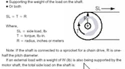
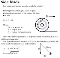
Side and thrust loads are considered major factors. These affect the bearing and seal life of the motor. Side loads occur when the motor drives a load through a pulley or sprocket, or when its shaft is supporting the load. Thrust load occurs when the shaft is being pulled on or compressed by the load.
Example 3
A brush mower's motor produces a torque of 1000 lb-in. to drive an 8-in. diameter pulley at 400 rpm. The side load created is 250 lb.
SL = 1000 (8/2) 250 lb
The created side load must be compared to the manufacturer's side load chart at the given motor speed to determine if it is within allowable operating conditions. If it isn't, a larger size, physical (not displacement) motor will need to be selected.
Properly sizing and selecting a motor starts with knowing all the operating conditions and factors. Once known, the task is painless, and leads to an efficient, productive, and long lasting tool.
| Pascal's law Hydraulic formulas Where, |
Phillip Groves is an applications engineer at White Hydraulics, Inc., Hopkinsville, Ky.


