This file type includes high resolution graphics and schematics when applicable.
The titanium hot forming process requires a high degree of precision. It involves heating parts and pressing them slowly in successive stages, waiting, and reheating several times before the process is complete. When large parts are involved, multiple hydraulic cylinders may be used to ensure that uniform positioning and force are being applied across the part. Such is the process employed by Missouri Metals, St. Louis, to manufacture precision titanium components for the aerospace industry.
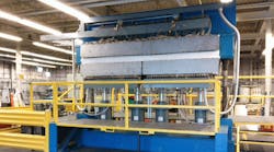
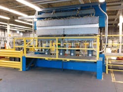
The company needed a new press to manufacture long, narrow parts of the metal—up to 28 in. by 128 in.—and Maintenance Manager Sam Moore decided it should be capable of pressing two parts at the same time. As a result, four hydraulic cylinders were used, two for each end of the press (Fig. 1). For pressing the longest parts, all four cylinders would be used for the cycle. If shorter parts were to be used, the system could be split and operated as two independent presses, with two cylinders each.
The new press operates at 1,700° F. The platens have heaters in them to soften the titanium for forming. The parts need to be pressed in stages; if the pressing goes too quickly, the material could crack. The solution is to close the press so that the platens just touch the metal, and initiate a pre-heat stage to make the titanium pliable. The press is then moved a few inches and the position is held for a time period, after which the process is repeated.
The final stage of the press operation is to apply a prescribed force, which can be up to 400 tons. “We can do up to 10 different press operations before we go to tonnage,” says Moore, “with position-hold times varying between one and five minutes.”
To develop the new titanium press, Missouri Metals contracted Valtech Hydraulics Inc., St. Louis, to design the hydraulics. They in turn subcontracted to John Henry Foster Inc. (JHF), also based in St. Louis, to implement the electronic controls.
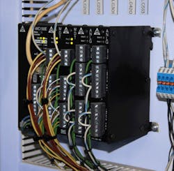
The electrohydraulic motion controller required a unit that could control both position and force—along with transitioning smoothly between these modes. The controller also needed to be able to synchronize the motion of multiple axes, which must move simultaneously. To fulfill these requirements, the RMC151 motion controller, available with up to eight axes of control from Delta Computer Systems (Fig. 2) was selected.
“After 20 years of industrial maintenance experience, the one thing that I’ve learned is to use a reputable product that doesn’t change frequently and for which spare parts are always available,” says Moore, who ratified the decision to use the Delta controller.
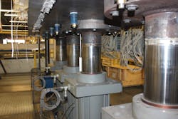
The four cylinders in the new Missouri Metals titanium press are mounted beneath the lower platen (Fig. 3) and push vertically up to close the press, which can operate in two modes: full platen (to press a single, very long part) and split platen (to independently press two parts).
Both modes of operation are set up using the custom feedback and cascade control features of Delta Computer Systems’ RMCTools development software.
Custom Feedback
Custom feedback is a programming option that enables the motion controller to perform mathematical or logical operations on a feedback value, or alternately, to combine the inputs from multiple feedback sources. The result is then incorporated as a single feedback value into the closed-loop control algorithm. In the Missouri Metals system, the cylinder positions must remain level during press operation.
To accomplish this, the position inputs from the four position transducers are averaged using custom feedback, which provides a target position for all cylinders to hit during the next control cycle. In addition, individual force values derived from each cylinder’s differential pressure transducers are summed to calculate the total system tonnage value, which is then compared with the force target value in the controller to use in its own closed-loop force calculations.
Cascade Control
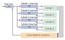
Cascade control is a control algorithm in which the output of one control loop provides the target for another loop. In the Missouri Metals design (Fig. 4), the inner loop run by each of the four individual cylinder axes is responsible for ensuring that its cylinder extends to the required position and delivers the set amount of force. The outer loops are responsible for determining the total response of the entire press system.
As described above, the target generated for the outer position loop using custom feedback is used to keep the cylinders perfectly level, while the target generated for the outer force loop ensures the forces exerted by each of the four cylinders add up to the predefined force set point. The inner and outer control loops run simultaneously, yet are independent of each other. This results in a perfectly level press platen delivering the set amount of force with no mechanical guides.
The cascade-control mode is set up by dedicating two of the controller’s motion axes to each cylinder. The “inner loop” is set up as a regular and faster closed-loop control axis and generates an output to the cylinder’s servo-quality proportional valve. The “outer loop” (the slower loop) is set up as a cascade axis, whose control output is used internally to the motion controller to provide a motion target to the inner loops. In operation, the overall system is controlled by writing commands to the outer-loop axis. All of this functionality is set up via simple write operations to registers within the RMC151—no complex motion programming needs to be done.
The press uses feedback from magnetostrictive linear displacement transducers (LDTs) attached to the sides of the cylinders to measure the position of each cylinder, and pressure transducers mounted in the cylinders (one on each side of the piston) as feedback to measure the force being applied by each cylinder. The outputs of the motion controller connect to four proportional servo valves that operate the cylinders.
During the initial steps of the cycle, the motion controller is set to control the position of the outer loop, ensuring that the individual cylinders are level while monitoring and limiting the total force being applied. The final step seamlessly transitions to force control to ensure that the press applies the specified tonnage.
“With the Delta RMC controls we’ve now got absolute control of position and pressure,” says Moore, “so we can run four cylinders simultaneously, or we can run two different press functions at the same time, and get a perfect part every time.”
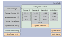
The system also contains a PLC for supervisory control. The Delta RMC connects to the PLC via Ethernet for PLC functions that include recipe storage, downloading motion instructions, monitoring motion results, and power-unit monitoring. A touchscreen operator interface (Fig. 5) connects via Ethernet to both the PLC and the Delta RMC for operator messaging, power-unit control, sequence control, and real-time monitoring of cylinder positions and forces.
“Synchronization is a big portion of our requirements,” continues Moore. “With the Delta RMC controlling the position of the cylinders, both cylinders are kept within a couple thousandths of an inch of each other during press operation in order to maintain the platens completely flat.”
Missouri Metals’ older machines weren’t able to maintain this level of precision because the quality of production depended heavily on the machine operator. “When it’s up to a person to open a hydraulic valve, you could have mistakes which result in wasted material,” says Moore. “Now, we keep from scrapping parts.”
In addition, operator productivity was limited in the case of older machines by the fact that an operator needed to be in attendance at the machine constantly during production. Now, the operator turns on the machine, selects the program, and pushes the “up” button. Then the operator places the part, presses the down button, and can move on to another machine. This makes machine operators more productive.
“We spent about $2 million to buy one of our other titanium presses from a manufacturer,” says Moore. “Because we went with best-in-class-components from different vendors, and built this machine in-house with a couple of integrators’ help, we were able to put this new press in production for less than half that cost.”
Jason Palmer is regional sales manager at Delta Computer Systems Inc., Battle Ground, Wash. For more information.
This file type includes high resolution graphics and schematics when applicable.
