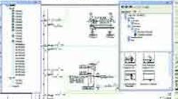
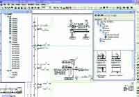
Latest software not only serves as a drawing, design, and training aid, but allows simulation by prompting the user for system parameters.
Symbols can be dragged into a library for subsequent simulation; they don't merely exist as graphics.
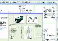
Opening a Properties dialog box for cylinders allows entering physical parameters, such as bore, stroke, and rod diameter.
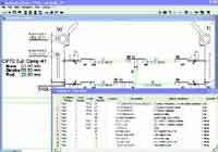
Tools for producing bills of materials proved quite useful and fairly flexible, but they were also a bit cumbersome.
In the field of schematic support software to design automated machines with fluid power systems and electrical controls, engineers have had to use either very high end mechanical CAD packages or low cost — but limited — twodimensional sketching software. Sometimes it is a combination of two packages, a standard CAD with a trade oriented add-on.
As the only fluid power designer for a large automation integrator, my responsibilities include circuit design, product specification, producing build drawings, integration, set up and troubleshooting of the designed circuits, and internal staff training. Previously, all drawings were produced in AutoCad, part numbers were manually entered into our purchasing system, circuit validation was performed after the build, and training was performed on the fly with the finalized product.
Six months ago, we adopted Automation Studio to do our pneumatic and hydraulic project document. This software not only provides features to draw schematics in a user-friendly and flexible manner, but offers strong documentation capabilities, tools to help size components, and fully animated and realistic simulation for pneumatics, hydraulics, and electrical controls.
In the beginning
To start drawing two-dimensional schematics, Automation Studio features a simple environment. This software is offered by Famic Technologies 2000 Inc., St.-Laurent, Que. All libraries come with a vast array of symbols. Thus, users do not have to draw basic, or even less common, symbols. If you cannot find the required symbol — for example, a valve with an uncommon spool configuration — Automation Studio offers the ability to construct those symbols using a component builder utility.
The symbols built into Automation Studio go beyond simple two-dimensional figures; they are linked to complex models and animation scenarios that later can be used in simulations. Newly made symbols can be dragged into a custom library for later use or to share with others. Again, when a symbol is calibrated during simulation and dragged into a library, it does not remain merely as a vector symbol. It is a fully tested component that can be used in other projects to conduct simulate an entire system.
Once component symbols have been dragged and dropped onto the workspace, pressure and pilot lines can be extended from one symbol to another to interconnect them simply by drawing lines from port to port. One especially useful feature is a rubber-banding line. Unlike traditional software, in which lines have to be redrawn whenever components are moved, Automation Studio's lines remain attached to components. This facilitates and accelerates design for new projects but also helps transform old projects into new ones. In our case, this feature alone could sometimes reduce redesign time threefold, which has a major impact on return on investment (ROI).
When you go beyond the mere drawing capabilities, this is where the package really outperforms any current available software — thanks to its ability to size components and to assign data and properties for later reporting and simulation.
Getting involved
Let's take cylinders as an example. Opening the Properties dialog box allows entering physical characteristics of the cylinder (bore, stroke, rod diameter, etc.) directly, or sizing the cylinder in accordance with a specific application. For example, if you know the forces or required extension time, a software sizing calculation sheet can help determine the size of the cylinder in accordance with known parameters. You can also enter the force applied to a cylinder as a function of extension, thereby allowing you to define a force profile as a function of the geometry of a machine element. These sizing calculation sheets are available for hoses, valves, pumps, and just about every fluid power component. To test Automation Studio's calculation sheets, we compared some of our calculations with those we made in the past in Excel. Total results were identical.
Simulation and education
Once a layout is completed and all connections made, the simulation mode can be accessed by a click on the Start button. At this point, you can simulate either one single diagram, the entire project, or a selection of schematics. Our welding line project had about 70 pages (diagrams), with a total of about 600 cylinders and valves. Due to its size, the whole system could not have everything simulated at once, but validating the system piece-by-piece proved very useful. At that size, we found the opening time for a project to be somewhat slow, but hardly worth mentioning.
In simulation, all components are animated and the line colors make it easy to follow high-to lowpressure and flow direction. To achieve greater accuracy in analysis, any simulated parameter (flow, pressure, position, etc.) can be graphed on a plotter and dumped into a data file for later review. This simulation is useful for checking the integrity of a design and to spot problem areas prior to machine implementation.
One of the greatest uses of the simulation is training for both in-house personnel and customers. Using Automation Studio at the engineering level allows creating a more flexible training environment at virtually no extra charge. Because most machine builders must provide this service, this feature has a big impact on ROI.
It fits the bill
Automation Studio's tools for producing bills of materials are fairly flexible. Granted, we found the interface to define the bill of material templates a bit cumbersome and sometimes irritating. However, their features are still better than
what is usually found in other software's tools, which are virtually non-existent. With Automation Studio's tools, you can gather data on each schematic, on a combination of schematics, or on an entire project. A filtering facility also allows the sorting components by technology, type, and so forth.
To expedite project documentation, we dumped a copy of our purchasing database into Automation Studio. This way, whenever we place a symbol from a drawing page, we can immediately assign a part number from the list and quickly obtain an entire project bill of materials. This task was not difficult or complicated, but took a lot of time, so we used interns to set up the database. In the short run, we have saved a substantial amount of time to produce documentation.
Summarizing the experience
Even though the software is quite user friendly and the learning curve is quick to start implementing schematics, the three-day training at the Famic facility in Montreal turned out to be one of the most productive moves we made. This package is very simple at first contact. However, learning how to master more advanced functions from the experts really made a difference to gain full advantage of the software's many benefits.
Perhaps the best experience was with tech support by phone. The technical staff was always able to answer all our questions, provide solutions, or present alternate solutions to our problems. Famic also provides services for the production of new symbols and simulation models when it is required.
Chris Goodlet is a fluid power designer at Prodomax Automation Inc., Barrie, Ont. He can be reached at [email protected] or by calling 705/726-5841.


