Hydraulic drives often are combined with gearing to provide the best combination of output speed and torque for maximum efficiency, performance, and controllability. But sometimes hydraulic actuators are best used when they are integrated into a gear drive. Hydraulically actuated clutches, for example, can be used within a gearbox to engage and disengage different sets of gears to provide different output speeds and torques.
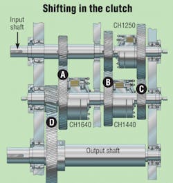
With no clutches engaged, the output shaft is in a neutral condition. That’s because with the input shaft turning, gearset A meshes, but the intermediate shaft does not rotate because the CH1640 clutch is not engaged. Likewise, gearset B meshes, but the intermediate shaft does not rotate because the CH1440 clutch is not engaged. Gearset C meshes, but the intermediate shaft does not rotate because the CH1250 clutch is not engaged. Importantly, all gear pairs are constantly in mesh, which eliminates the need to synchronize shaft speeds for shifting.
To drive the output shaft 400 rpm (lowest speed, highest torque), the CH1640 clutch is engaged. This clutch transmits up to 390,000 lb-in. of torque at 1600 rpm to allow gearset A to drive the intermediate shaft. The intermediate shaft then drives the output shaft through gearset D, which has a 4:1 speed reduction to yield an output speed of 400 rpm. The other two clutches are still disengaged, so only gearset A transmits power.
A median speed of 450 rpm is achieved by disengaging the CH1640 clutch and engaging the CH1440 clutch, which transmits up to 270,000 lb-in. at 1800 rpm. So power is transmitted from through gearset B to drive the output shaft through gearset D.
For the highest speed, 500 rpm, the CH1250 clutch is engaged, again, with the other two clutches disengaged. This transmits up to 180,000 lb-in. of torque at 2000 rpm through the CH1250 clutch to gearset C. Output shaft speed, then is 500 rpm.
The clutches require only pilot hydraulic fluid for actuation. In this application, fluid pressure of 150 psi is required, although CH series clutches can accommodate oil pressure to 200 psi. Therefore, the clutches could be (and often are in other applications) actuated with compressed air. The CH 1250, 1440, and 1640 clutches require only 45, 79, 101 in.3 of fluid, respectively, to fully actuate.
Because Logan’s CH series clutches rotate with the shaft and gear to which they are mounted, pressurized fluid cannot be routed to their housing, as would be done with a stationary mounted clutch. Instead, fluid is routed into the end of each respective shaft through a rotating union. Engagement and disengagement is controlled simply by routing pilot fluid through a 2-way directional valve.
Other configurations
Logan offers the CH series in seven standard sizes with maximum torque ratings from 49,000 lb-in. (5532 N-m) to 1,280,000 lb-in. (144,000 N-m). However, other configurations are available to serve a wide variety of marine, mobile equipment, and stationary applications.
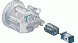
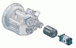
For example, PTO clutches have standard SAE J744 or SAE J620A flanges for mounting the clutch between a machine’s PTO, bell housing, or pump drive box and hydraulic pump. The clutch allows engaging the hydraulic pump only when needed. The clutch normally consumes no power — only a small volume of air or oil for engagement. More importantly, with the clutch disengaged, the hydraulic pump consumes no power because it doesn’t even rotate. This can yield substantial energy savings, even with variable displacement pumps. That’s because even when rotating a zero displacement, a variable-displacement pump still produces torque drag on the power train. The Logan PTO clutch can also be used to disengage a pump to keep it from overspeeding when the vehicle runs at highway speed.
For more information on Logan clutches, visit www.loganclutch.com or email [email protected].
