A new or rebuilt hydraulic system should be flushed before it becomes operational. The concept of flushing is to loosen and remove contamination particles inside the system by forcing flushing fluid through it at high velocity. In theory, this leaves the inside walls of the fluid conductors at the same cleanliness level as the new fluid to be installed. Then, during normal operation, the system will experience only externally and internally generated contamination that can be controlled with filtration.
Instructions for flushing usually specify a level of system cleanliness that must be achieved, and sometimes a fluid velocity that must be maintained during the flushing procedure. Typical instructions state that flushing must be accomplished at normal system fluid velocities for a certain period of time, with a certain level of filtration. More stringent specifications may call for a particular fluid contamination level and require documentation by fluid-contamination analysis.
One shortcoming of all these flushing methods is that they are based on procedures to clean the fluid, but ignore the system’s interior cleanliness. Even if the tubing and conductors were installed with the greatest of visual care, the human eye can only see particles that are larger than 40 µm—well below the needs of even the crudest and most elementary hydraulic system.
How High a Velocity?
The critical variable in flushing to achieve acceptable fluid and conductor cleanliness is fluid velocity. Traditional flushing methods usually establish this velocity in one of two ways:
- The velocity must be high enough to achieve a Reynolds number (NR) of 3,000 or more.
- The velocity must meet or exceed the system fluid’s normal operating velocity as designed.
Experience has shown that neither of these flushing velocities is sufficient to assure the cleanliness of the inside diameter (ID) of the system’s conductors. A short review of basic fluid dynamics explains why.
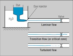
Dimensionless Reynolds numbers are used (along with other factors) to classify fluid flow as either laminar, turbulent, or transitional (somewhere in between). Reynolds numbers depend on the fluid’s viscosity and velocity and the ID of the pipe or tube. The flow condition that exists when NR is less than 2,000 is termed laminar, signifying orderly flow with parallel streamlines. When the Reynolds number is greater than 3,000, the flow becomes turbulent, defined as the condition when fluid streamlines are no longer orderly. Flow exists in transition for Reynolds numbers between 2,000 and 3,000; this is sometimes called the critical zone.
The hydraulic fluid velocity required to achieve turbulent flow is well within the recommended fluid-velocity guidelines for hydraulic fluid conductors. This equation reinforces that statement:
NR = V × D/v
where V is the fluid velocity in ft/sec, D is the ID of the fluid conductor in ft, and v is the fluid kinematic viscosity in ft2/sec.
First Example
Suppose the Reynolds number is 3,000, the conductor is a 1-in. tube with a wall thickness of 0.049 in., and v is 1.288 × 10⁻⁴ ft2/sec. Calculated fluid velocity, then, is 5.14 ft/sec., which corresponds to a flow rate of 10.24 gpm.
Note that the viscosity (and therefore, the Reynolds number) of a typical hydraulic fluid is influenced by temperature and pressure. That is, the hotter the oil, the higher the Reynolds number for the same fluid velocity and pressure. And the higher the pressure, the lower the Reynolds number for the same fluid velocity and temperature. Thus, specifying that Reynolds number should be 3,000 is not a stringent requirement, but is well within the normal operating fluid velocities of a system. By definition, turbulent flow has been created because the fluid-stream lines are no longer parallel. However, sufficient fluid motion to clean the inside walls of the conductors has not been generated.
Even at the recommended maximum fluid velocities and Reynolds numbers for hydraulic-system working conductors, fluid flow still is not turbulent enough to greatly affect contamination on conductor walls. Boundary-layer fluid at the interior surfaces of the fluid conductor remains undisturbed.
Second Example
The Reynolds number for flow at normal system velocities next can be calculated using the same conductor size and kinematic viscosity as in the first example, but with the velocity increased to 20 ft/sec. This higher velocity results in a Reynolds Number of 11,671, which corresponds to a flow rate of 39.8 gpm.
As the Reynolds number increases, flow conditions go from laminar, through the critical zone, to turbulent. It has been proven empirically that once the Reynolds number exceeds 3,000, resistance to fluid flow is a combination of the effects of turbulence and of viscous drag at the conductor wall. (This region of viscous drag at the conductor wall is known as the viscous sublayer.) A transition zone exists within the turbulent flow range where flow resistance goes from being governed by turbulence effects to being governed by the roughness of the conductor’s inside wall.
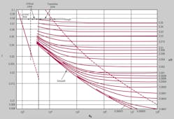
This is shown clearly when inspecting the Moody diagram which graphically demonstrates the relationship between Reynolds number, friction factor f, and the roughness of the conductor’s inside surface, e. Resistance to flow through a fluid conductor, represented by the friction factor, is only affected by the surface roughness of the fluid conductor when the Reynolds number exceeds 4,000. Thus, the majority of the resistance to flow is created by turbulence effects. Only when the Reynolds number is high enough to cause surface projections of the conductor walls to extend beyond the viscous sublayer does the surface come in contact with the turbulent flow and affect the pressure drop in the conductor.
Surface Roughness
Average surface roughness for drawn tubing e is 0.000005 ft. If the conductor has the same 1-in. tubing with 0.049-in. wall thickness, the ratio of roughness to ID will be 0.000067. The Moody diagram indicates that the Reynolds number for this conductor must be at least 25,000 before the inside surface exposes its resistance to fluid flow.
To ensure the inside wall of the conductor will be cleaned, the Reynolds number must be greater than 25,000. For flow to occur fully in the rough zone of turbulent flow, the Reynolds number must be greater than 3.25 × 10⁷. Using 1.288 × 10⁻⁴ ft2/sec—the same fluid kinematic viscosity as in the first example—a Reynolds number of 25,000 corresponds to a fluid velocity of 42.8 ft/sec (a flow rate of 85 gpm), still easily attainable with conventional hydraulic pumps.
Real-World Systems
It can be argued that if the walls of a conductor are not greatly affected by normal system fluid velocities, contaminants lodged there will have little chance of entering the fluid stream. This may be partially true, but the argument applies only to smooth, straight conductors at steady flows and pressures. It is not representative of normal installations that combine straight runs, bends, and numerous fittings where flow patterns are only predictable empirically, and where pressure fluctuations and spikes are commonplace.
Depending on the severity of service that the system will experience, pressure spikes will dislodge contaminants held in the walls of the conductors and between fitting interfaces. In critical systems, 3- to 25-μm particles can significantly impact system performance. The only way to guarantee that conductor contamination (which can be released at any time during operation) does not affect system performance is to protect each component with a filter, an option so costly that it would not be used in most systems. Although flushing hydraulic-system conductors at the normal system operating fluid velocities can provide fluid velocities higher than flushing at a Reynolds number of 3,000, the inside wall of the conductors still will not be cleaned.
High-Velocity, High-Pressure Flushing
Flows that produce Reynolds numbers of 25,000 are needed to ensure that conductor walls are exposed to turbulent flow. Because system conductors may consist of pipe, tube, and/or hose and associated fittings, the specification of a contractual number for the Reynolds number is difficult and still does not guarantee that conductors will be cleaned. The best you can do is establish conditions that will maximize the Reynolds number. These conditions consist of the highest possible velocity at the lowest possible fluid viscosity. Limiting factors are the conductor’s pressure rating and the fluid’s maximum operating temperature.
When flushing a system, the valving and actuators must be “jumpered” for safety reasons so that the only resistance to fluid flow is the pressure drop in the conductors and fittings. When flow becomes turbulent, the pressure drop is proportional to the square of the velocity. Extrapolating this relationship to its maximum, the highest possible velocity occurs when the pressure drop in the conductor generated by fluid flow is equal to the maximum test pressure of the conductor. Flushing a system at these high flows and pressures has the added advantage of expanding and contracting the conductors and fittings as the pressure fluctuates while inducing highly turbulent flow. This optimizes the flushing action.
By equating the pressure drop in a conductor to the maximum pressure rating of that conductor, the maximum fluid velocity possible, along with the corresponding Reynolds number, can be calculated. The temperature of the fluid directly affects its viscosity and is the other variable that can control the Reynolds number. Flushing pressure also affects viscosity, but this is hard to quantify because pressure in the pipe being flushed will vary from maximum at the pumping source to atmospheric at the conductor outlet.
The equation used to calculate head loss in the turbulent zone is:
HL = f × L × V2/(2D)
where HL is head loss, f is the friction factor found in the Moody diagram, and L is the conductor length in ft.
This equation will calculate the maximum velocities and Reynolds numbers that can be achieved for any given maximum flushing pressure.
Determining friction for pipe flow requires iterative calculations using the Moody diagram. Given the pressure rating, ID, length, and relative roughness of the conductor, assume a friction factor and then calculate the fluid velocity. Next calculate Reynolds number and determine a new friction factor from the Moody diagram. Repeat the calculation until the friction factor converges.
The flushing table shows velocities and Reynolds numbers that have been calculated for 200 ft of Schedule-80 pipe using the maximum test pressure for the pipe and a surface roughness of 0.00015 ft for wrought-iron pipe. These calculations did not take into account the pressure drop produced by the various fittings normally used, so the values for the attainable fluid velocities and Reynolds numbers are optimistically high. Also, fluids with lower viscosities or flushing at higher temperatures to reduce the fluid viscosity can increase the Reynolds number.
The values determined for maximum flushing velocity and flow rate indicate that some of these conditions—mainly for lines with inside diameters smaller than ¾ in.—can be satisfied using conventional high-pressure pumps of appropriate flow capacity. However, it may be difficult to induce the pressure fluctuations needed to dislodge contaminants. For systems with larger conductors, special methods must be used to achieve the necessary pressures, fluid velocities, and Reynolds numbers to properly flush the lines.
Clean Hose Prevents Contamination Troubles
Research has proven that clean oil and a clean hydraulic system are the keys to longer system life and less downtime. However, clean oil can be contaminated by particles left behind from the cutting, crimping, bending, and flaring process, creating a real problem. Attempts have been made to solve this problem by using chemicals, high-pressure flushing, and pull-through techniques with marginal results.
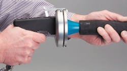
A relatively new cleaning technique offers an effective and practical alternative to these procedures: Sponge-like projectiles are shot through hose and tubing assemblies by a blast of compressed air. Equipment for this procedure is much more affordable than that for high-velocity flushing. Perhaps even important, though, is that it cleans assemblies much more effectively than compressed air alone and in a fraction of the time it takes for high-velocity flushing.
Launchers fire the projectile (which is sized 20% to 30% larger than the ID of the hose, tube or pipe), stripping out the internal contamination as it travels through couplings and around bends, forcing the contamination out in front of it.
Once the hose assembly is cleaned, be sure to install protective caps or plugs at both ends to prevent contamination from entering the assembly. These should not be removed until the hose assembly is being installed on the equipment.
This article was originally authored by Patrick Jones of Consolidated Fluid Power Ltd., Dartmouth, Nova Scotia.


