Motion control is the simultaneous control of acceleration, velocity, and position for performing a useful task. The critical concept in this statement is that all three variables—acceleration, velocity, and position—are under control. A review of some basic electrohydraulic designs will help pave the way to understanding the concepts of motion control. Two conventional hydraulic circuits will be used to illustrate the point: discrete, or so-called bang-bang directional control, and open-loop proportional control.
These two circuits will lead us to an ultimate solution: the electrohydraulic positional servomechanism. It will be shown that when the electrohydraulic servo is properly designed — and the control system is suited to the task—the result is a true motion control system meeting the divergent goals of increasing machine productivity and product quality, while reducing overall production costs.
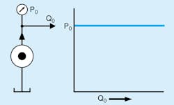
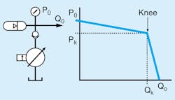
Hydraulic system designers should realize early in the design process that a power unit providing constant pressure to the control valve is best suited to the motion control task. The ISO symbol for a constant pressure source, along with a plot of its behavior, is shown in Fig 1. A real-world constant-pressure source is shown schematically in Fig. 2. It normally consists of a pressure-compensated pump augmented by large accumulators to accommodate the sudden flow demands of a servo or proportional valve and a check valve to prevent the pump from having to cross over center in order to absorb any flow that might otherwise be forced back into the pump.
Figure 2 also shows the pressure-flow characteristics of a conventional pressure-compensated pump. At low pressure, it behaves as a fixed-displacement pump, delivering nearly constant flow, neglecting internal leakage. When pressure reaches the knee value, PK, the pump's pressure compensator becomes active, and the displacement automatically decreases with rising pressure. Thus, at pressures above PK, the pressure-compensated pump acts very nearly as a constant-pressure source. It certainly is safe to deadhead this pump with closed-center valves without danger of overpressurization.
Discrete Control
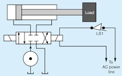
In a conventional electrohydraulic control system (Fig. 3), a simple, solenoid-operated directional control valve can operate in only three discrete states: centered (off), shifted to the right to route flow in one direction, or shifted to the left to route flow in the opposite direction.
To understand the problems, imagine that limit switch LS1 in Fig. 3 is closed, the right-hand solenoid is energized, and the cylinder is moving the load to the right at a speed determined by the supply pressure and the valve flow coefficients. At some point, the load engages the limit switch, which causes the directional valve to center and thus block all ports. The load will decelerate rapidly, subject to its mass, the cylinder’s size, and how quickly the control valve shifts. Severe shock and vibration can occur before the load actually stops, especially if the load mass is great.
In the event of large shocks, machine members experience high stress levels that can shorten their lives. Very high pressure peaks—or spikes, as they are frequently called—also will occur. These pressure peaks can overstress the hydraulic components, including the cylinder tube and seals, leading to premature leakage and failures. The external vibration can move the entire machine, putting mechanical stresses on the plumbing, which can lead to fitting failure.
In the oscillatory stopping process, the frequency of the vibration can be measured if one has force, pressure, or speed sensors whose outputs can be displayed on an oscillographic recording instrument. With the recording, the frequency of the vibration can be measured. This frequency is called the hydromechanical resonant frequency (HMRF) and can be calculated using any of several methods. (Space limitations prohibit discussing HMRF in detail, but for more information on this important topic, see this article from the author.)
The potential for self-destruction is probably the biggest shortcoming of the discrete control system. However, poor repeatability of the stopping point can also be a serious drawback. When system designers use a limit switch to initiate deceleration, they normally do it because the application needs to stop the load at some predictable and controlled position. Unfortunately, in the discrete system, several random effects cause considerable variation in the ultimate stopping point. The actual stopping time is a complex function of:
- magnitude of the load’s mass,
- shift time of the valve,
- timing of the land shut-off within the valve,
- valve internal leakage,
- cylinder internal leakage,
- friction in the cylinder and load,
- fluid viscosity, and
- scan time of the digital controller (PLC), if used.
AC solenoids produce valve shift times that are affected by the instant within the AC power line 60- or 50-Hz sine wave when switching takes place. The random variation in shift time of the valve will be at least the time of one-half a line cycle (8.3 msec in the 60-Hz system or 10 msec in the 50-Hz system). This adds to the normal random variations in the valve shift time.
Load and cylinder friction also contribute random variations. These are affected by system temperature, as is the viscosity of the process fluid, which imposes its own variations into the stopping time. If a digital controller is used, the random variation in stopping time will be at least equal to one full scan interval. The slower the digital controller, the greater the variation. The net result is that when the system of Fig. 3 is tested for repeatability, the actual stopping point will vary considerably from trial to trial.
Proportional Control
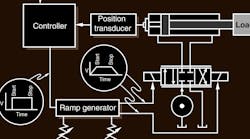
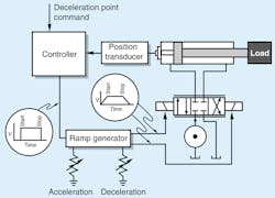
Figure 4 shows the second step toward motion control, which uses a proportional valve instead of the discrete directional valve. As with Fig. 2, the schematic diagram is not complete; rather, it is intended only to point out the obvious advantages of using proportional rather than on-off control. Note that the cylinder is outfitted with a position sensor that measures the position of the piston relative to the cylinder tube. The sensor works full-time—it is always sending an analog output signal to the controller.
The controller is depicted as a digital device into which a deceleration point can be entered, probably by means of a conventional keyboard. Being a digital device, it can give its attention to only one item or task at any given instant. That is, when it “looks at” the deceleration set point, it cannot be looking at the position sensor output. There must necessarily be a time lag between these two events. Additionally, the PLC probably has many other tasks that will divide its attention, such as monitoring and controlling temperature, reservoir level, and more. The resulting delay is the scan time of the controller, and it dictates how well the system performs.
Thus, we see that each of the tasks is actually serviced at regular intervals. The total time lag between the instant when one task—say, monitoring the position sensor output and the instant when it does so again—is the total scan time. Furthermore, the instant when an event occurs will not be synchronous with the instant that the controller actually looks and sees the event. This results in random variation in the stopping point.
Continuing around the loop of Fig. 4, note that the output of the controller consists of the start-stop signal, which is generated based on a comparison between the deceleration setpoint and the actual position from the position sensor. Also note that the start-stop signal from the controller is not connected directly to the valve solenoids. Rather, it is connected through the ramp generator.
The ramp generator is a common option on many proportional valve amplifiers. It ramps up the output until it equals the command voltage if the command input goes to a high level. Without the ramp, the amplifier output would jump up almost as quickly as the command signal from the controller. But with the ramp generator, even if the command is a step (as shown in the figure), the output is a signal to the valve coil that changes slowly. This prevents the spool from suddenly jumping to a proportional position. Instead, the spool slowly opens or closes, giving a considerable degree of acceleration control.
The ramp circuit is outfitted with trim pots to allow the user to adjust the rate at which the output changes, thus controlling the rate at which the valve spool shifts. This constitutes a vital improvement over the on-off control offered in the discrete directional system because the shocks are significantly reduced. Furthermore, the adjustability of the ramps gives the user immediate feedback as to the effectiveness of the adjustments.
A Case in Point
In a typical operational scenario, imagine that the start command has been given, the valve spool has ramped to a proportional position, and the cylinder is extending at some desired speed. Now suppose that the position sensor puts out a signal of, say, 1 V for every inch of travel away from the cap end of the cylinder, and that the deceleration setpoint is set to 6 V. We then expect that the deceleration will be initiated when the cylinder extends to 6 in. This is the progression of events:
In the early parts of the cycle, the cylinder will be at a position less than the 6 in.—6 V from the position sensor. Next, the controller obtains the position signal and compares it to the deceleration setpoint. Because the setpoint is greater than the feedback signal, the controller issue a high output, commanding the valve to be open.
The piston continues extending and eventually will reach a position of 6.0000 in. Assuming perfect calibration, the position sensor will be generating 6.0000 V. Unfortunately, the controller will not be looking at the position sensor at that instant—the likelihood is very nearly zero. Instead, it will look only after the cylinder has over-traveled slightly. The amount of overtravel depends on the PLC scan time and the piston velocity at the instant the scan takes place.
At any rate, the position feedback sensor output eventually will exceed the deceleration setpoint value, and the controller will get around to scanning the sensor. The comparison will be made and judged to have resulted in over-travel, and the controller will issue a stop command.
The stop command merely means that the command will go to zero within a few milliseconds, perhaps even within a few microseconds of detection. But because of the ramp generators, the valve will not center quickly. Instead, it brings the cylinder to smooth and gentle stop. This will have been an effective means for controlling shock and vibration. And to some extent, it will have overcome the challenges from having a low hydromechanical resonant frequency.
The Next Step: Motion Control
Clearly, the proportional valve control method can tame a wild machine axis. However, the system as presented thus far is not perfect. The most serious deficiency is the uncertainty as to where the cylinder and load will eventually stop. There is no means to back up should there be overtravel. Therefore, almost all the random factors that affect the stopping point of the discrete directional system will be visited upon this, the proportional system.
A system that is proportional for its shock control, but also monitors and controls position on a full-time basis, is called the electrohydraulic positional servomechanism. It possesses all the desirable characteristics for effective motion control, but because it is a bona-fide feedback control system, it introduces its own set of challenges. However, when properly designed and tuned, this system provides the ultimate solution to the most demanding motion control application challenges.
The positional servomechanism is normally considered a positioning system. However, when the concept of profiling is superimposed, the result is motion control—total control of the machine. To be successful, motion control must have three things designed into it:
- a command motion profile,
- sufficient power to manage the load at the required speeds, and
- sufficient closed-loop bandwidth to meet accuracy and stability requirements.
The motion-control profile is crucial to the motion control system, and represents the most significant contribution of the digital computer to the motion-control process. The profile is the means by which acceleration, velocity, and position are controlled simultaneously. Profiles are very easily generated by a digital computer (motion controller card or circuit board), and are formulated at design time to determine the peak speeds that must be attained by the actuator based on a stated productivity rate.
In determining these peak speeds, we must first collect data on the productivity needs of the application. For example, suppose the application requires stamping out 30 packets of paper plates per minute. Immediately, we know that the cycle rate is 12 cycles per second. Further, if we are given that cylinder stroke must be, say, 4 in., and that the cylinder must remain extended for 0.5 sec., then we know that the actuator must fully extend and retract within 1.5 sec. We can add some reasonable acceleration times, plus take into account that the cylinder does not naturally want to retract as fast as it extends. (Yes, this statement is correct for the valve-controlled cylinder.) To compensate for this, we can rob a few milliseconds from the extension time and give it to the retraction time. This allows us to reach conclusions about the maximum speed needed in order to achieve the required productivity rate.
This example leads us to the conclusion that the peak extend speed will have to be about 10 in./sec. Once we are given the maximum thrust force, we can design for a given supply pressure, which makes it possible to completely size the critical components in the system. Our example introduces the idea of a motion profile, which is a means of defining the speed, acceleration, and position of the cylinder and load at any instant within each cycle and throughout each and every cycle for the entire life of the machine.
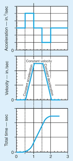
The relationship between acceleration, velocity, and position —which are drawn against a common time axis—is represented in Fig. 5. Newton revealed through the calculus that:
- velocity is the integral of acceleration
- position is the integral of velocity
- velocity is the derivative of position, and
- acceleration is the derivative of velocity.
Even if you never studied calculus (see "Calculus Simplified" below), these are mathematical facts of our physical world. What they mean to the motion control system designer is that specifying any one of these three parameters for all time automatically specifies the other two as well. This is because of their undeniable relationship to each other—they are all integrals or derivatives of each other.
This relationship makes it possible to achieve the simultaneous control of acceleration, velocity, and position, even though the final system closes the loop with position feedback only. It works like this: The position profile, the plot at the bottom of Fig. 5, is the actual command to the motion-control servomechanism. The slope of the position profile represents the velocity of the output at each and every instant in time. The slope of the velocity profile is the acceleration profile, which is actually carried in the curvature of the position profile. So the designer controls acceleration by controlling the curvature of the position command profile.
The final result is this: For merely having fed the position command profile to the motion control servo axis, all three dynamic variables are implicit in that profile. Furthermore, designing a servo axis that faithfully follows the command profile, controls all three parameters. This is the sum and substance on modern motion control philosophy.
At design time, the design methodology recommends that the entire motion control profile, acceleration, velocity, and position, be synthesized based on productivity and other motion needs. In contrast, at commissioning time the programmer of a dedicated motion controller card may only specify that the motion must go from, say, position x to position y with maximum speed of v and maximum acceleration of a. The digital motion controller interprets these as instructions, then generates the actual profile commands on the fly. Consequently, the programmer may never see the entire profile itself.
This information was provided by Jack L. Johnson, PE, an electrohydraulic specialist, consultant, former director of the Fluid Power Institute at the Milwaukee School of Engineering, and contributing editor to Hydraulics & Pneumatics. He can be reached via e-mail at [email protected].
Calculus Simplified
Simple algebra defines the slope of any line as the difference between two points on the y axis divided by the difference between two points on the x axis. Because the y axis represents position, the difference between two points is distance. Likewise, the x axis represents time, so the difference between two points is the time it took to travel the respective distance.
So the slope of a line plotted as position versus time is distance travelled divided by time travelled, which, by definition, is velocity. Likewise, the slope of velocity is acceleration. Calculus simply extends this concept further by calculating slope of a line or curve at any instant by breaking it into infinitely small steps instead of at one place.
