The purpose of flow control in a hydraulic system is to regulate speed. All the devices discussed here control the speed of an actuator by regulating the flow rate. Flow rate also determines rate of energy transfer at any given pressure. The two are related in that the actuator force multiplied by the distance through which it moves (stroke) equals the work done on the load. The energy transferred must also equal the work done. Actuator speed determines the rate of energy transfer (power), and speed is thus a function of flow rate.
Eight different types of flow-control valves are commonly used in hydraulic systems.
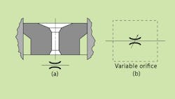
Orifices—A simple orifice in a hydraulic line, Fig. 1(a), is the most elementary method for controlling flow and can also be used as a pressure-control device. When used to control flow, the orifice is placed in series with the pump. An orifice can be a drilled hole in a fitting, in which case it is fixed; or it may be a calibrated needle valve, in which case it functions as a variable orifice, Fig. 1(b). Both types are non-compensated flow-control devices.
1. Simple fixed orifice (a) and variable orifice (b) flow controls.
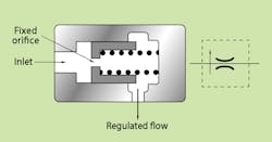
Flow regulators—These devices, Fig. 2, are slightly more sophisticated than a fixed orifice and consist of an orifice that senses flow rate as a pressure drop (∆P) across the orifice. Also, a compensating piston adjusts to variations of inlet and outlet pressures. This compensating ability provides closer control of flow rate under varying pressure conditions. Control accuracy may be 5%, possibly less with specially calibrated valves that operate around a given flow-rate point.
2. Flow regulator adjusts to variations in inlet and output pressures.
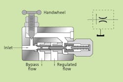
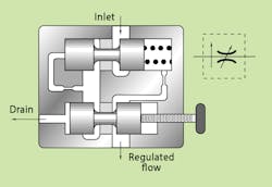
Bypass flow regulators—In this flow regulator, flow in excess of set flow rate returns to reservoir through a bypass port, Fig. 3. Flow rate is controlled by throttling fluid across a variable orifice regulated by the compensator piston. The bypass flow regulator is more efficient than a standard flow regulator.
3. Bypass flow regulators return excess flow from pump.
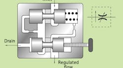
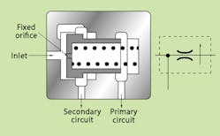
Demand-compensated flow controls—Flow controls can also bypass excess system flow to a secondary circuit, Fig. 4. Fluid is routed at a controlled flow rate to the primary circuit, and bypass fluid can be used for work functions in secondary circuits without affecting the primary one. There must be flow to the primary circuit for this type of valve to function—if the primary circuit is blocked, the valve will cut off flow to the secondary circuit.
4. Demand-compensated flow control bypasses full pump output to tank during idle portion of work cycle.
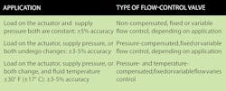
Pressure-compensated, variable flow valves—This flow control is equipped with an adjustable variable orifice placed in series with a compensator. The compensator automatically adjusts to varying inlet and load pressures, maintaining an essentially constant flow rate under these operating conditions to accuracies of 3% to 5%, Fig. 5. Pressure-compensated, variable flow-control valves are available with integral reverse-flow check valves (which give fluid unrestricted flow in the opposite direction) and integral overload relief valves (which route fluid to tank when a maximum pressure is exceeded).
5. Pressure-compensated, variable flow-control valve adjusts to varying inlet and load pressures.
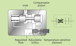
Pressure- and temperature-compensated, variable flow valves—Because the viscosity of hydraulic oil varies with temperature (as do the clearances between a valve’s moving parts), output of a flow-control valve may tend to drift with temperature changes. To offset the effects of such temperature variations, temperature compensators adjust the control orifice openings to correct the effects of viscosity changes caused by temperature fluctuations of the fluid, Fig. 6. This is done in combination with adjustments to the control orifice for pressure changes as well.
6. Pressure- and temperature-compensated, variable flow-control valve adjusts the orifice size to offset changes in fluid viscosity.
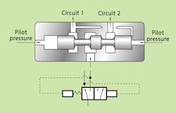
Priority valves—A priority valve, Fig. 7, is essentially a flow-control valve that supplies fluid at a set flow rate to the primary circuit, thus functioning as a pressure-compensated flow-control valve. Flow in excess of that required by the primary circuit bypasses to a secondary circuit at a pressure somewhat below that of the primary circuit. Should inlet or load pressure (or both) vary, the primary circuit has priority over the secondary — as far as supplying the design flow rate is concerned.
7. Priority valve supplies a set flow rate to a primary circuit.
The best type of flow-control valve to use depends on the design parameters of the application. Above are general guidelines based on common application characteristics.
