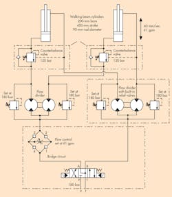
The schematic of a hydraulic circuit shown here represents a portion of a pipe-making machine. The machine processes a coil of sheet steel by rolling it into a cylindrical shape that is subsequently welded and cut to length for use in the gas and oil industry. The schematic demonstrates how a bridge circuit works to ensure that fluid can only flow one way through a pressure-compensated flow-control. But the central component doesn’t have to be a flow control. It could just as well be a filter or any other component that requires unidirectional flow.
With the directional valve shifted to the left, fluid exits Port A and enters the bridge circuit. Check valve 4 prevents fluid from flowing to the upper left, so fluid flows to the upper-right through Check valve 1. Check valve 2 blocks flow, so fluid flows to the left, through the orifice. Backpressure works to keep Check valve 4 closed, so fluid flows through Check valve 3 to the flow divider.
This partial circuit shows several useful hydraulic functions used in a steel processing machine.
When the directional valve shifts, return fluid from the flow divider can’t get past Check valve 3, so it flows through Check valve 2. Check valve 1 blocks any additional downward flow, so, as it did before, fluid travels through the orifice to the left. Backpressure keeps Check valve 3 closed, so fluid flows through Check valve 4 and into the directional valve’s B port.
The pressure-compensated flow control regulates the flow into and out of the cap-end of the cylinders. The entire circuit is designed to keep the two lifting cylinders level as they lift heavy rolls of coiled sheet steel that eventually will become large-diameter pipe for the oil-and-gas industry. This circuit has more interesting aspects, so let’s not stop here.
With the directional valve shifted to the left, fluid flows from its A port, through the bridge circuit, flow divider, and pair of counterbalance valves to the cap end of both cylinders. Because the pressure-compensated flow control in the bridge circuit regulates flow going into the cylinders, this is a meter-in circuit. However, when the directional valve shifts to the right, fluid eventually works its way into the cap end of the cylinders. This fluid does not go through the flow control in the bridge circuit, but fluid leaving the cap end does. So this becomes a meter-out circuit when the cylinders are retracting. The counterbalance valves were installed as a safety function in case the flow control or check valves would fail.
Now notice the two flow dividers. The one on the left splits flow and sends it to the cap ends of the two cylinders through a pair of counterbalance valves. Fluid free-flows through each counterbalance valve’s check valve, and fluid from the rod ends is routed to the flow divider on the right side, where flow is combined to a single return flow to Port B of the directional valve. The flow divider on the left is sized larger to handle more flow than the one on the right. That’s because flow from the cap end of the cylinders is greater than the flow going into the rod end when the cylinder is retracting.
Also, the relief valves around the flow dividers allow one cylinder to be a little faster from possible blow-by on the dividers and cylinders. When the slightly faster cylinder bottoms out, the flow divider section to the lagging cylinder continues to be driven and forces the other half to continue to move intensifying its out let pressure to the cylinder. The relief valves open to protect the circuit from over pressurization. Each cycle causes the cylinders to reset on the extend and the retract strokes.
This discussion was provided by Robert J. Sheaf Jr., contributing technical expert to Hydraulics & Pneumatics and president of CFC Industrial Training, Fairfield, Ohio. In addition to providing industrial training, CFC also provides consulting for new fluid power and electrical systems and troubleshooting of existing ones. For more information, call (513) 874-3225 or visit www.cfcindustrialtraining.com.


