A user’s request for an HPU design that would eliminate a free-standing unit and all its plumbing on the factory floor, and instead be incorporated into a machine structure, led to a compact system that also is more energy-efficient at a lower overall cost. The new unit was designed by MFP Automation Engineering.
It provides clamping force during a testing phase in the user’s machine cycle. During that phase, it provides high flow to move a part rapidly into the clamp position but needs almost no flow to remain clamped at pressure until the test phase is complete. At the end of the test phase, it again provides high flow for unclamping and part removal. Because the high flow is only required for approximately 6 sec. of an 81-sec. test cycle, the application was an ideal candidate for energy reduction.
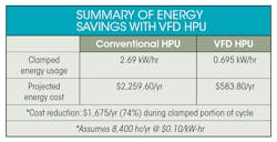
The reductions in size and energy consumption were made possible primarily by switching from a typical induction motor to a PMAC motor with a VFD controller. Moving the unit from the factory floor to the machine envelope makes additional floor space available for other uses. Total energy savings at full flow are approximately 10% because the PMAC motor eliminates the magnetizing current that occurred with the induction motor. The most significant energy reduction occurs during the clamped phase of the machine cycle because the motor speed is reduced. The new design also reduces overall system costs. Although net costs of major components for the VFD and PMAC motor design are approximately 10% higher, simplification of the valves required to control the unit resulted in lower overall costs.
System Components
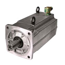
The HPU is driven by a Parker Hannifin NX series brushless servomotor with a continuous nominal torque rating of 132 lb-in. (15 N-m) and intermittent power capabilities of up to 13.6 hp (10.1 kW). For the majority of the machine’s cycle time, during which its operation is sequential, it delivers a nominal 4.6 hp (3.4 kW) at 2,200 rpm, although it can range between 1.3 hp (0.97 kW) and 6.7 hp (4.9 kW) during this phase. Motor speed is controlled by the machine cycle, based on flow demands of the various functions. This eliminates the need for separate flow controls and minimizes wasted energy.
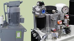
A redesigned hydraulic power unit uses a variable-frequency drive that reduces energy consumption as much as 74% over a conventional constant-speed HPU.
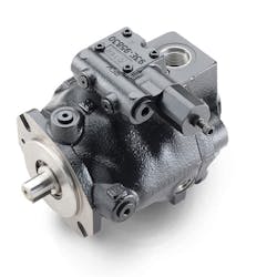
The pump is a Parker PD018 variable-displacement axial piston pump, with a rated displacement of 18 cc/rev and a maximum rated continuous pressure of 4,000 psi. This application uses a standard direct-operated pressure compensator, set at 1,500 psi. Many servo-driven applications use a fixed pump to hold pressure and slow the drive to maintain pressure in the clamped or static condition. The compensator used here allows the pump to stroke back to a minimum displacement. This reduces the servo motor’s torque and current draw and addresses the user’s concerns about high motor temperature and potential touch/heat hazard on the machine. The torque and motor current of most fixed pump systems remain constant from idle through pressure, but the displacement in this system drops from 0.55 in.3/rev (9cc/rev) to 0.11 in.3/rev (1.8 cc/rev). The motor current drops almost proportionally, as does the amount of heat generated and energy consumed.
The conventional and redesigned power units both use Parker’s PD01 variable-displacement, axial-piston pump, which is rated for continuous pressure of 280 bar and is designed for high-speed, low-noise operation.
Also included in the system is a maximum-volume limiter that is set at 0.55 in.3/rev (9 cc/rev) which yields 7 gpm (25.5 lpm) at the designed rpm for this application. The pump’s speed range is 50 to 3,700 rpm. An added benefit of the pump design is its Ripple Chamber technology, which softens pressure pulsations at the pump’s outlet by 40 to 60%. This reduces system noise significantly without the added expense of noise-dampening components.
Other system components include an integrated manifold that permits filtration through an automotive-spec pressure filter and return filter. Also incorporated is a small air/oil cooler that provides air flow around the PMAC motor and also helps cool the fluid, as required by the unit’s smaller reservoir. Controls on the machine include a 10-station manifold assembly with seven Parker D03 directional-control valves, four Parker pilot-operated check valve modules, four direct-operated pressure-reducing valves, and two counterbalance modules for the vertically-supported loads.
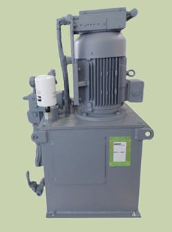
This conventional HPU not only consumes more energy than its VFD HPU counterpart but is also substantially larger—a 594-in.2
The new system replaces a conventional HPU consisting of a 5-hp induction motor, also driving a Parker PD018 piston pump and including a pilot-operated compensator with heat exchanger and an automotive-spec pressure and return filter. The conventional system also included an eight-station manifold assembly with seven Parker D03 directional valves, four Parker pilot-operated check modules, seven pressure-reducing valves, five flow controls, and a BSPP-ported steel manifold.
The new VFD-driven power unit provides better control over pump speed and dramatically reduces the package size above the tank lid. The VFD reduces operating cost by lowering the speed of the pump when it is in a steady-state condition. The variable-flow, pressure-compensated pump delivers only the flow needed when at pressure. Lower energy usage also reduces heat generation, allowing a footprint with a smaller tank to be used without affecting the machine performance. In addition, better control over speed and flow reduces manifold, resulting in fewer potential leak points and failure modes.
Energy savings comparison shows cost reduction of VFD-powered unit over conventional system.
Some systems combine a conventional drive and similar pump with load sensing and an accumulator, which allows a smaller pump and motor to be used and still delivers intermittent max flow. However, the VFD power supply used in this system can provide feedback about the health of the HPU and the machine itself. Not only does the power supply match demand more closely and simplify the system by reducing components, it facilitates mapping the machine initially and monitoring torque, current, and speed to detect degradation in the machine’s performance throughout its life.
Roger Betten is president, MFP Automation Engineering, Hudsonville, Mich. For more information, call (616) 538-5700, or visit the company's website.
