This file type includes high-resolution graphics and schematics when applicable.
Power in electric and hydraulic systems is perfectly analogous. For hydraulic circuits, power is calculated as the product of flow and pressure:
Power = W = P × Q
where W is power (watts), P is pressure (N/m2), and Q is flow (m3/sec).
Electrical power is the product of voltage and current:
W = V × I
where V is voltage (N•m/coulomb) and I is current (coulomb/sec).
Self-Heating Hydraulics
Any time a hydraulic flow undergoes a drop in pressure, or any time a current undergoes a drop in voltage, energy converts to heat because of a path restriction. If energy is not producing force or torque and speed, then it is inefficient, causing self-heating in the circuit. In electrical circuits, the heat energy is generated in, and imparted to, the element that contains the friction.
In hydraulic circuits, heat energy is caused by the shearing of the fluid as it squeezes through small passages. The fluid then transports the heat to other parts of the circuit. Whether electric or hydraulic, self-heating can cause damage if it is not transferred out of the circuit. Heat exchangers are the method of choice for either system.
A common description applied to heat generation is that it is a consequence of the losses in the system. If all components were 100% efficient, self-heating would not be a problem.
In hydraulic machinery, temperatures that are too low will cause oil-based fluids to become so viscous whereby the pump cannot move the fluid. All of the pump’s work will be directed toward shearing the fluid, resulting in highly localized hot spots that create their own set of problems, especially if there is insufficient fluid throughput to replace the heated oil with cold oil. Self-destruction of the pump can occur.
If the fluid is water-based, the obvious result is that the fluid will freeze. Water-based fluids are viable in indoor applications, but cannot be used for mobile machinery in freezing environments.
To alleviate low-temperature problems with oil-based fluids, heaters are occasionally installed to sustain temperature during shutdown periods. In extreme arctic conditions, diesel engines may be kept running 24/7 with some hydraulic fluid circulating at all times.
Clearly, very low temperatures are a problem with hydraulic equipment; therefore, self-heating effects can be put to use to protect against cold. However, the problem is that the self-heating process is going on the entire time the machine is running, and excessively high temperatures are a continuing problem in both systems.
Hydraulic systems, like electric systems, will recover from extreme cold, provided that mechanical power is not applied to the pump input shaft. That is, permanent damage is not the result of the excessively low temperature alone; rather, it is the combination of cold and trying to get the pump to turn over mechanically.
Friction and Resistance
As already stated, friction is the cause of all heating in all functioning systems. Mechanical types of friction are caused by the relative motions of moving parts, plus the friction that causes shearing of the fluid as it is forced through small clearances.
Resistance is a kind of electrical friction. It is measured and quantified in ohms, the MKS unit of electrical resistance. Current through resistances causes self-heating effects. All electrical elements have some resistance. Resistance is as unavoidable in electric circuits as friction is in hydraulic circuits. Hydraulic resistances have no quantifying unit of measure, a fact that is holding back the development of useful circuit-analysis theorems and methods.
ResistancesValve control is notoriously inefficient. It is referred to as the “energy loss method of control.” That is, the pump generates more power than is required by the load, and the operator changes the amount of opening of the valve (it is a variable resistance) to absorb the excess power and deliver just the right amount to the load.
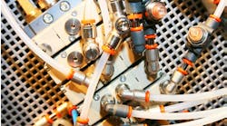
There are series restrictions to fluid flow in all circuit elements, including the plumbing, flow-distribution manifolds, and valve subplates. Each restriction results in the fluid undergoing a drop in pressure and a subsequent rise in temperature. Every turn and elbow in the flow path contributes to the pressure drops.
Hydraulic Heat Exchangers
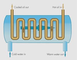
Water-to-oil heat exchangers are viable and often used in in-plant, stationary applications, because there is usually some source of cooling water. It consists of an outer shell that carries the cooling water, and an inner tube that carries the hydraulic fluid to be cooled.
Of interest is the fact that the two internal fluid flows are opposite to one another. The oil moves from right to left in the figure while the water moves from left to right. This method puts the warmest water in proximity to the warmest oil and vice versa. It assures that there is always a temperature gradient between the two flowing media.
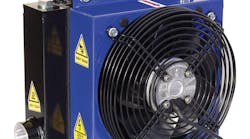
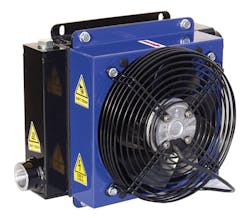
Air-to-oil heat exchangers are vital to mobile equipment because they use the ambient air as the means for carrying the heat from the hydraulic circuit. Just a quick glance at the heat exchanger in Fig. 2 shows its similarity to an automobile’s radiator. They use exactly the same technology, including a fan to stimulate adequate air flow through the radiator cooling coils. Thin vertical tubes carry the hydraulic fluid. Very thin horizontal fins are attached to the tubes, providing heat-radiating area—a good friend of effective heat transfer.
Electrical Self-Heating and Heat Exchangers
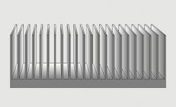
Heat exchangers used for electric circuits are called heat sinks. Heat sinks need to be applied to the component that has the resistance, because electrical heat energy is imparted to that component. In contrast to hydraulic circuits, and as stated earlier, hydraulic heat energy is imparted to the fluid and can be carried to other parts of the circuit for removal. Electrical heat has to be carried away at the point of generation.
A heat sink, depicted in simplified form in Fig. 3, consists of a solid base, usually made of aluminum because of its heat-conducting characteristics, plus a number of fins in a variety of shapes. The heat sink in the figure can be found attached to the central processor unit in your computer.
The heat sink’s underside is flat and smooth, and attaches to the smooth and flat top of a processor chip with heat-conducting adhesive. Due to the very high clock speeds and extremely high transistor density of modern processor chips, self-heating becomes severe to the point where a fan must be mounted on top of the heat sink to increase air flow over the fins.
Resistance, Conductivity, and Self-Heating
Just as conduit paths (plumbing, subplates, and manifolds) in hydraulic circuits have unavoidable restrictions and tortuosity, so do electrical circuits. Copper is the wire material of choice, but silver and gold may be called for when the lowest possible conductor resistance is required. No matter the conductor material, conductivity is not perfect, so resistance becomes inevitable.
Power loss and self-heating are equally inevitable, but it is a matter of degree relative to each individual component. The current through a light-emitting diode may not heat up enough to require heat-removing equipment, but it may be the case for an electric motor or the voltage regulator in a computer’s power supply.
Like electric motors, solenoids are made of wound coils of wire wrapped around some iron core material. Laminated cores reduce the internal heating effects from core losses. Both the wire resistance—often referred to as copper losses in the jargon—and the core losses contribute to self-heating.
Electric motors, whether ac or dc, have self-heating and many implement built-in cooling features. One method is to cast cooling fins into a motor’s external housing. Other motors have a small fan attached to the rotor with end openings to allow for constant flushing of air through the innards of the machine.
Electric and hydraulic systems can operate at temperatures above the threshold of human pain. Both can operate reliably and continuously at temperatures that are downright dangerous to man and beast and require respect and protective design practices. Because hydraulic self-heating is imparted to the circulating fluid, the entire circuit is at elevated temperature at nearly every point and element.
Electric circuits confine self-heating to certain circuit components. An ac solenoid may cause burns if touched, but the driver amplifier controlling it may be at or near room temperature. However, caution is the byword when working with all power-conversion equipment. It may be hot.
