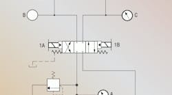
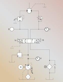
A company in Italy has a wire drawing machine that makes specialty wire for the aerospace industry. A shuttle driven by a hydraulic motor clamps the beginning of the alloy wire and pulls it through a forming die. Maintaining proper tension on the wire is important, and the pulling force from the clamping shuttle is controlled by a pressure reducing valve. Speed of drawing is controlled by a meter-out flow control.
The hydraulic motor drives a sprocket and roller chain that oscillates the clamp shuttle back and forth, pulling the wire and reversing to grab a newly cut end. The wire needs to be straight and eventually cut into 25-ft lengths. Different alloys and wire sizes require different pulling forces and draw speeds. To this end, the operator originally had to manually adjust the speed and pull forces when the machine was changed over for a different wire.
The wire manufacturer was developing a very light weight wire, which required very low pulling force, and problems occurred when the shuttle returned to the starting position. The directional valve shifted, and the shuttle started to reverse, but at a very slow speed. It didn’t make sense to the operators because there was no speed control for the return cycle.
They figured there must be something wrong with the pilot operated directional valve, so they replaced it with a new one. When the system still reversed in a creep mode, they replaced the pressure reducing valve, also to no avail.
Any idea what the problem could be?
Robert J. Sheaf Jr., is the founder of Certified Fluid Consultants (CFC) and President of CFC-Solar Inc. CFC-Solar provides technical training, consulting, and field services to any industry using fluid power technology. Visit www.cfc-solar.com for more information.
Find the solution
Think you know the answer? Submit solutions to [email protected]. The correct answer will also be published in the next edition of “Troubleshooting Challenge.”
Congratulations to Bert Martinez, CFPE, engineering team lead for manifolds and systems at Sun Hydraulics Corp., Sarasota, Fla., who was the only person to answer correctly for our November ”Troubleshooting Challenge."
All correct solutions will be entered for a chance at a $50 gift card — we will randomly select a winner from all correct answers. The winner’s name will be printed in the next edition of “Troubleshooting Challenge.”
Solution to December’s bow thruster hydrostatic problem
Aeration problems can show up on evaluations as lack of lubrication, high inlet vacuum, or low charge pump pressure, to name a few causes of failures. The hydrostatic system on the cruise ship reused an existing old fuel oil tank. This type of tank normally has baffles positioned horizontally to reduce the splashing of oil when used on moving mobile type equipment. The new hydrostatic system used the large existing couple at the bottom of the tank for the intake line but used the existing coupling mounted in the side, located close to the top for the case drain and filter loop returns.
The total return line flow was 50 gpm into these couplings, which did not have any stand pipes directing the flow below the fluid level. The high return flow discharging above the fluid level was the oil to foam, entraining excessive air and causing the system failures.
Stand pipes were installed to direct the return oil flow below the fluid level and eliminated the aeration problem.


