This file type includes high resolution graphics and schematics when applicable.
Gear pumps often are considered only as sources of constant flow due to the fixed-displacement constraint of their design. However, accessories and integral, bolt-on valve options are available to increase the functionality of these workhorses, lowering system costs and improving system reliability. With these alterations, gear pump performance can approach that of more expensive and complex piston pumps.
For instance, eliminating the plumbing between the pump and in-line directional valve by mounting the valve directly on the pump helps control costs. Fewer fittings and connections reduce leakage, which improves reliability. Moreover, locating valves at the pump itself boosts performance by lowering recirculation pressures. Following are examples of circuits that can improve the functionality of basic gear pumps. Some are tried-and-true basic circuits, while others take a more innovative approach.
Unloading circuits
Unloaders combine the high-flow capabilities of tandem pumps with the low-power requirements of a single pump. Fluid flows from both pump sections until a predetermined pressure and/or flow is achieved, depending on the design. At that threshold, one pump section begins recirculating fluid from its outlet to its inlet, which reduces flow output of the pump to the remaining section. This, in turn, reduces the pump’s power requirement to slightly over that needed to operate the still-pressurized section. The percentage of reduced flow depends on the ratio of the displacement of the unloaded section to the displacement of both sections. Integral or bolt-on unloading valve circuits reduce or eliminate tubing, hose, fittings, and their potential for leakage.
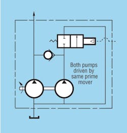
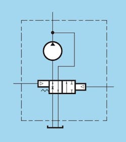
The simplest unloader is manually actuated, Figure 1. A spring holds the unloader valve’s spool either open or closed until a manual action actuates the valve. A lever or other mechanical operator is the simplest method of actuating the valve. Pilot-operated (using air or oil) unloader valves represent the next level of sophistication, because they allow remote operation. The highest level of sophistication is a solenoid-operated valve controlled by electrical or electronic switches. This technology allows not only remote operation, but automated control by microprocessors as well, which usually would be regarded as overkill for applications using such a simple unloading technique.
The manually actuated unloader often is used in a circuit to achieve high flow for rapid movement and reduced flow for fine control, such as in a bohttp://hydraulicspneumatics.com/200/Issue/Article/False/83396/Issueom with rapid extension capability. The circuit in Figure 1 delivers high flow until the unloader valve is energized. To deliver low flow with the valve in its normal (non-energized) state, a normally open valve would be used.
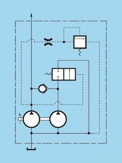
The pressure-sensing unloader is the most common design. In this unloader, Figure 2, a spring holds the valve’s spool in its high-flow position. At a predetermined pressure, a relief valve opens to allow hydraulic pressure to shift the spool to the low-flow position. The pressure-sensing unloader most often supplies fluid to cylinders needing rapid rod extension, followed by low-speed, high-pressure operation at the end of a stroke. The pressure-sensing unloader is basically an automatic version of the manually actuated unloader that reacts to system pressure. Familiar applications include log splitters and hydraulic vises.
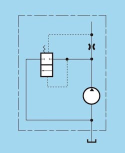
The spool on the flow-sensingunloader, Figure 3, also is held in its high-flow position by a spring. However, a fixed orifice in the valve is sized to the flow requirement of a machine at an optimum engine speed. As engine speed exceeds this optimum range, the pressure drop across the orifice increases to shift the spool to its low-flow position. This design results in lower fuel consumption, quieter operation, and lower initial system cost, because components downstream from the pump can be sized for the restricted maximum flow. Flow-sensing unloaders typically are used to limit circuit flow to an optimum range for improved overall system performance and to limit loop pressures during over-the-road travel. Common applications are refuse trucks.
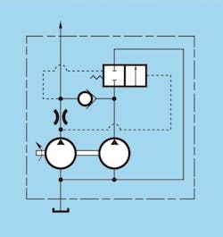
The pressure-and-flow-sensingunloader spool also is held in the high-flow position by a spring, Figure 4. Either a predetermined pressure or flow, whichever is reached first, triggers the unloading function. High-pressure work can be completed at either idle or at normal operating engine speeds. This feature reduces unnecessary flow, thereby lowering required power. Pressure-and-flow-sensing unloaders typically are applied in excavating equipment because of the wide variations of loads and speeds encountered.
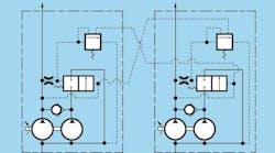
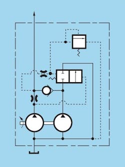
A pressure-sensing unloader with power summationcircuit consists of two slightly modified pressure-sensing unloader pumps driven by the same prime mover, Figure 5. Each pump receives a pilot unloading signal from the other unloading pump; this is known as cross sensing. Cross sensing allows high-pressure operation of one pump and high-flow operation of the other. Integral relief valves can be set to unload one or both pumps at a particular pressure in each circuit. This option reduces power demand for the pumps, so a smaller, more economical prime mover can be used.
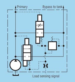
Load-sensingunloaders, Figure 6, are used, not surprisingly, in a load-sensing circuit. When the main control valve handles are in the neutral position, no load-sensing signal exists. Therefore, all pump flow diverts to the tank. Applying a load-sensing signal from the control valve directs pump flow to the circuit. When the pump outlet pressure reaches a predetermined value above the load-sensing signal, pump flow is metered-off to the tank. Thus, only the pump flow needed for the function is supplied to the control valve.
The advantages of a gear pump with a load-sensing unloader over a piston pump are lower component costs, better contamination tolerance, and less intensive maintenance associated with the simpler components. A load-sensing unloader might be applied to vary conveyer motor speed on a potato harvester.
Priority flow control
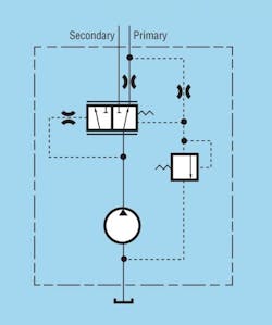
A constant-primary-flow-control valveensures a constant flow of hydraulic fluid to a machine function, regardless of pump speed, function pressure, or flow requirements of branch circuits. In this circuit, Figure 7, pump output must equal or exceed the flow requirement of the primary circuit. Secondary flow can be applied to other applications or routed back to tank. The constant-primary-flow-control (proportional) valve combines a priority function with the pump to eliminate plumbing and external leakage points and, ultimately, reduces cost. This gear pump circuit typically is used in power steering applications, because it eliminates the need for a second pump. It often is found in lift trucks.
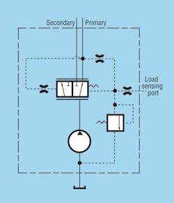
Load-sensing flow-control valvesfunction much like constant-primary-flow-control valves: they provide primary flow regardless of pump speed, function pressure, or flow requirements of branch circuits. However, with this design, Figure 8, only the flow necessary for the primary function is delivered through the primary port, up to the set maximum flow. This presents an alternative to delivering a constant maximum flow from a standard priority-flow control. The no-load loop pressures are lower than with the constant-primary-flow version, leading to lower circuit temperatures and lower no-load power requirements. Like the constant-primary-flow-control valve, the proportional load-sensing flow-control valve typically is designed for power-steering applications.
Bypass flow control
With bypass flow control, Figure 9, pump output is restricted to a predetermined maximum, regardless of pump speed or function pressure. Any flow greater than the maximum is returned to tank or the pump inlet. This design limits fluid flow to a function, which optimizes performance. The benefits of this design include initial system cost savings by sizing the circuit to the set maximum flow of the control. Integrating the valve with the pump reduces leakage points and plumbing, and recirculating loop pressures are minimized by the close proximity of the bypass to the pump.
Bypass flow control valves can be designed with a closed-center, load-sensing control valve to limit function operation within a prescribed flow range (function speed). This type of a gear pump circuit often is designed for refuse trucks to limit the hydraulic operation to optimum engine speed or for power-steering pump circuits. It can also be used in stationary equipment.
Inlet dry valve
The inlet dry valveis an air-actuated control that throttles the inletof a pump and allows only a minimal (<5 gpm) flow through the pump when the machinery hydraulics are not under load. The control allows full flow to the pump during the loaded mode. This circuit, Figure 10, eliminates clutch assemblies needed to disengage the pump from the prime mover, thus helping to control costs. It also reduces no-load power requirements, because the minimal flow through the hydraulic circuit leaves more power from the prime mover available for driving the vehicle. Additionally, the lower flow through the inlet dry valve circuit reduces pump noise when no-load operation occurs. A dry valve system can be designed for any vehicle with an on/off hydraulic system driven by a primary engine, such as a refuse packer truck, as well as for industrial equipment.
Choosing a pump design
Operating pressures of gear pumps today are approaching those of piston pumps, and integral load-sensing options provide gear pumps with the ability to provide variable flows. This means the once-clear choice between gear pumps and piston pumps has become increasingly cloudy.
The single most common determining factor in choosing the appropriate pump is total system costs. Gear pumps, with their lower initial costs, less complex circuitry, and lower filtration requirements can offer a viable alternative to more costly piston equipment in many applications.
For more information, contact the author at [email protected] or visit www.parker.com/gearpump.
This file type includes high resolution graphics and schematics when applicable.
