The hydraulic filtration industry uses the ISO 4572 Multipass Test Procedure to evaluate filter element performance. During the Multipass Test, fluid circulates through the test circuit under precisely controlled and monitored conditions. The differential pressure across the element being tested is continuously recorded, while a constant amount of contaminant is injected upstream of the element. On-line laser particle sensors measure the contaminant levels upstream and downstream from the test element. The results of this test depend heavily on flow rate, type of contaminant, and terminal pressure differential.
The Multipass Test determines an element’s:
· dirt-holding capacity,
· pressure differential of the test filter element, and
· separation or filtration efficiency, expressed as a beta ratio.
Contaminant loading
Contaminant loading in a filter element refers to filling and blocking of pores throughout its media. As contaminant particles load the media’s pores, fewer open paths remain for fluid flow, so the pressure needed to maintain flow through the media increases. Initially, differential pressure across the element increases slowly because fluid can still pass through open pores. The gradual pore-blocking process has little effect on overall pressure loss.
|
Beta ratio helps determine filter efficiency Beta ratio (also known as the filtration ratio) is a measure of a filter element’s particle-capture efficiency. Therefore, it is a performance rating. Here is how a Beta Ratio is derived from Multipass Test results. Assume that 50,000 particles, 10 µm and larger in size were counted upstream from the test filter, and 10,000 particles in that same size range were counted downstream from the filter. Applying the equation:
ßx = NU ÷ ND Therefore, ß10 = 50,000 ÷ 10,000 = 5. This result would be read as “Beta ten equals five.” A beta ratio number by itself means very little; it is a preliminary step to finding a filter’s particle-capture efficiency. This efficiency, expressed as a percent, can be found by a simple equation:
Ex = 100 × (1 – 1/ß) In this example, the particular filter element tested was 80% efficient at removing 10-µm and larger particles. For every five particles in this size range reaching the filter, four were trapped in the element. |
Eventually, successive blocking of pores significantly reduces the number of pores open for flow. The differential pressure across the element rises exponentially as it nears its maximum life. As the element continues to load with contaminant, the pressure differential across the filter continues to increase. This goes on until the bypass valve (if installed) opens, the element (if without bypass protection) fails structurally, or the clogged element is replaced.
Every filter element has a characteristic relationship between pressure differential and contaminant loading. This is the filter element life profile, which is affected by system operating conditions such as variations in system flow rate and fluid viscosity.
Bypass valves
Bypass valves open flow paths around filter elements to prevent their collapse or bursting when they become loaded with contaminant. As contaminant builds up, the differential pressure across the element increases. At a pressure well below the filter element’s failure point, the bypass valve opens, allowing flow to go around the element. Some bypass valves have a bypass-to-tank option that directs unfiltered bypass flow back to reservoir through a third port, preventing unfiltered bypass fluid from entering the system.
Some upstream contaminant particles can bypass the filter element with fluid and enter the downstream system, compromising filter element effectiveness and degrading fluid cleanliness.
Some filters are designed with no bypass valve (often called a blocked bypass). They prevent unfiltered flow from going downstream, protecting servovalves and other contaminant-sensitive components. In filters without bypass valves, higher collapse-strength elements may be needed, especially if installed in high-pressure locations.
When specifying a non-bypass filter design, make sure the element has a differential-pressure rating close to the system’s maximum operating pressure, and that the filter has a condition indicator. This device will signal when the element is loaded to the point that it should be cleaned or replaced. Calibration marks indicate if the bypass valve has opened. Generally, indicators are set to trip at a differential pressure anywhere from 5% to 25% below that which opens the bypass valve.
Sizing housing and element
The filter housing size should be large enough to achieve at least a 2:1 ratio between the bypass valve setting and pressure differential of the filter with a clean element. For longer life, this ratio should be 3:1 or even higher.
The filter specifier must know the fluid’s operating viscosity and the maximum flow rate to ensure that the filter does not spend a high portion of time in bypass due to flow surges. This is important in return-line filters, where flow multiplication from large cylinders may increase return flow compared to pump flow rate.
Consider ambient temperature conditions when sizing filters. Low ambient temperatures may increase fluid viscosity to the point where pressure differential across the filter assembly also may increase considerably.
If a filter was fitted with a 50-psi bypass valve, the initial (clean) pressure differential should be no greater than 25 psi and preferably 16 2/3 psi or less. These pressures are calculated from the 3:1 and 2:1 ratios of the 50-psi bypass setting and initial pressure differential.
Standard filter assemblies normally come with bypass-valve cracking pressure between 25 and 100 psi. The bypass valve in most of these assemblies limits maximum pressure drop across the filter element. As the element becomes blocked with contaminant, pressure differential increases until it reaches the bypass valve cracking pressure. At this point, part of the flow through the filter assembly begins to bypass the element through the valve. This limits the maximum pressure differential across the filter element.
The relationship between the starting clean pressure differential across the filter element and the bypass valve pressure setting is very important. A cellulose element has a narrow region of exponential pressure rise. This in effect determines the element’s useful life.
In contrast, the useful element life of single-layer and multi-layer fiberglass elements is established by the nearly horizontal, linear region of relatively low pressure drop increase, not the region of exponential pressure rise. Accordingly, the filter assembly’s bypass valve cracking pressure, whether 25 or 75 psi, has little impact on the element’s useful life. So, initial pressure differential and bypass valve setting is less a sizing factor for fiberglass media.
Filter types and locations
The major filters incorporated into a hydraulic system—suction, return, pressure, and off-line—are defined by where they are placed. A filter’s location in the circuit is the primary determinant of its maximum rated pressure.
Suction and return line filters are generally designed for lower pressures—500 psi or less. Pressure filter locations may require ratings from 1500 to 6000 psi.
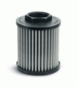
Suction filters are located upstream from the pump’s inlet port to protect it from relatively large contaminants in the fluid. Some may be simple inlet strainers, submersed in fluid in the reservoir. Others may be mounted externally. Suction filters have relatively coarse elements to prevent restricting flow to the pump. Some pump manufacturers recommend not using a suction filter, so check for inlet restrictions. For this reason, suction filters are not used as a system’s primary protection against contamination, resulting in a decrease in their use in modern hydraulic equipment.
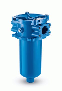
Return filters may be the best choice if the pump is sensitive to contamination. Usually, they are the last component through which fluid passes before entering the reservoir. Thus, they capture wear debris from all working components and any particles that enter through worn cylinder rod seals before such contaminant can enter the reservoir and be pumped back into the system. Because this filter is located immediately upstream from the reservoir, its pressure rating and cost can be relatively low.
Retracting some cylinders with large diameter rods may result in flow intensification. This high return-line flow rate may open the filter bypass valve, letting unfiltered fluid to pass downstream.
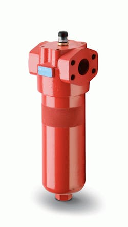
Pressure filters are located downstream from the pump. They handle system pressure and are sized for a specific flow rate in the pressure line where they are located. Pressure filters are especially suited for protecting sensitive components, such as servovalves, directly downstream from the filter. Because pressure filters are located just downstream from the pump, they help protect the system from pump-generated contamination.
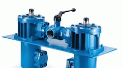
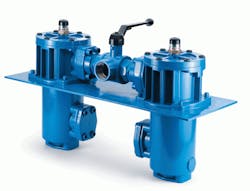
Duplex filters may include pressure and return filters. They provide continuous filtration, with two or more filter chambers and necessary valves to allow for uninterrupted operation. When one filter element needs to be serviced, the duplex valve is shifted, diverting flow to the opposite filter chamber. The dirty element can be changed, while flow continues to pass through the cleaner element. The duplex valve typically is an open cross-over type to prevent flow blockage.
Off-line filtration
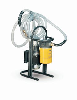
This popular filtration arrangement—also called recirculating, kidney loop, or auxiliary filtration—is totally independent of a machine’s main hydraulic system, so it is attractive as a retrofit project. An off-line filtration circuit includes its own pump and electric motor, a filter, and required connecting hardware. These components are installed off-line as a small subsystem separate from the working lines, or they may be included in a fluid-cooling loop. Fluid is pumped continuously out of reservoir, through the off-line filter, and back to reservoir. A rule of thumb: the off-line pump should be sized to flow a minimum of 10% of the main reservoir volume.
With its polishing effect, off-line filtration is able to maintain fluid at a constant contamination level. As with a return line filter, the off-line loop is suited to maintain overall system cleanliness; it does not protect specific components. An off-line filtration loop is relatively easy to retrofit on an existing system that has inadequate filtration. Also, it can be serviced without shutting down the main system.
The information in this article was compiled from our Fluid Power Handbook. For more information, check our Basics section.
