Content has been updated as of Oct. 13, 2021.
The following four pneumatic circuits can be used for air preparation, double-acting cylinders, continuous cycling and hand control applications. They can also be subsystems in larger circuits.
Air Preparation
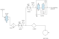
Before compressed air is used in a pneumatic device, it must be properly prepared so that it does not damage components. Here is a schematic (below) for a pneumatic device that prepares compressed air coming from a single source.
Putting the manual shut-off valve or pneumatic isolation/lockout valve first makes it easier to maintain the FRL and it protects downstream equipment when depressurizing the system for maintenance. For safety, operators should be able to lock the valve in the off position. If it is necessary to have clean, dry air flowing through the valve, the valve can be mounted after the FRL.
In the diagram, the filter (FIL01) is just downstream from the shut-off valve (VLV01) to remove particulates and moisture. The triangle at the bottom of the symbol indicates that this filter has a liquid drain, which can be manual, semi-automatic or automatic. Although the regulator (REG01) is downstream of the filter, the two could be a single unit, indicated by a dashed-line box around both filter and regulator. Although not shown in this diagram, it is good practice to note the machine’s working and maximum pressures. A tag with this information is often located close to the regulator.
A pressure gauge (GAU01) should always be included with a regulator, whether built-in or threaded into the regulator’s pressure port. Although not shown in this schematic, a pressure switch can be installed just downstream of the regulator to monitor pressure. This switch’s output typically gets routed to a programmable logic controller or some other machine controller.
A regulator can offer relief, reducing output air when either the regulator is adjusted to a lower pressure or to remove downstream pressure when upstream air is exhausted. Triangles at the upper left corners of the regulator symbols (REG01 and REG02) show they are the relieving type. The exit air regulator (REG01) provides clean, dry and filtered air that can be split through a T fitting or pneumatic distribution block.
One line then provides lubricated air and the other provides non-lubricated air. The non-lubricated line feeds a second regulator that supplies the electrically operated soft-start/dump valve (VLV02). This valve typically acts as a safety device by relieving pressure from motion-causing pneumatic devices, such as cylinders and actuators, when an emergency stop is pressed.
For applications such as pneumatic tools and motors which need to be lubricated, that lubrication should consist of light oiling to prevent clogging these devices.
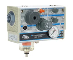
Installing circuits such as this can be simplified by using a device that contains all the air-preparation components and controls (below). It also includes a clogged filter indicator, adjustable pressure switch with indicator LEDs and port sizes that adjust to match the need flow rate needed.
Double-Acting Cylinder
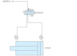
The schematic below shows a common automation application: using a 4-way solenoid valve (SOL01) to extend and retract a double-acting cylinder (CYL01). Triangles at each side of the symbol indicate it is a pilot-activated, single-solenoid, spring-return valve.
Filtered air feeds the solenoid valve, which is usually energized by a 24 V dc PLC output. This activates the valve and lets air leave through port B and flow freely through the flow control to extend the cylinder rod and plunger to the left. Air on the left side of the cylinder is forced out through its flow control to the valve’s port A, and then goes to port R and exits through a muffler to reduce exhaust noise.
Pilot valves need only a small amount of air to efficiently move a large valve spool. However, valves require a minimum operating pressure, typically about 20 psi, to move the spool. A spring on the left side pushes the valve spool to the right to maintain its normal off or resting state. With the valve off, air flows out of port A and freely through the adjustable flow control to the left side of the cylinder (CYL01), making it retract.
As the cylinder retracts, air on the right side leaves through an adjustable flow-control device. As the device’s check-valve closes, air in the flow section can be adjusted to throttle the cylinder retraction. The flow-controlled air then goes through the valve’s port B and leaves at port S through a muffler.
Continuous Cycling Cylinder
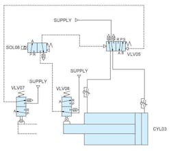
Pneumatic components can be combined to cycle automatically without external controls (see schematic below). It shows compressed air controlled by three valves (VLV05, VLV07 and VLV08). And when the solenoid (SOL06) is energized while the cylinder (CYL03) is retracted, the system starts cycling to extend and retract the cylinder.
Supply air flowing through VLV08 and SOL06 provides pilot air to the directional control valve (VLV05). The air supplied through this valve makes the cylinder extend and retract (cycle) in a similar fashion to the double-acting cylinder in the circuit above. To control cycle speed, flow control valves adjust the flow of air from the cylinder.
As the cylinder extends, it operates the 3-way, 2-position spring-returned valve (VLV07). which supplies pilot air to VLV05. The pilot air changes the valve spool’s position, which reverses the cylinder’s direction and retracts it. With the cylinder retracted, VLV08 is actuated, supplying pilot air to the other side of VLV05 and making the cylinder reverse direction and extend. The cycle repeats until the solenoid is de-energized, which ends the cycle once the cylinder retracts.
The 4-way, air-piloted, directional control valve (VLV05) and the two 3-way roller-actuated valves (VLV07and VLV08) are this circuit’s key pneumatic logic components. Unlike electrical solenoids, they use air to control the 4-way valve’s spool position and are configured like limit switches with a mechanical arm. The valves are actuated by cams or flags on the cylinder and, when not activated, the valves spring-return to their normal position.
Two-Hand Control
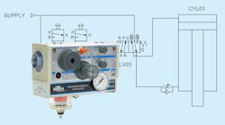
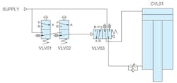
The circuit for a two-hand safety control system for a press application (schematic below) features two pneumatic buttons (VLV01 and VLV02) configured as 3-way valves. They feed pilot air to a 4-way valve (VLV03). Both buttons must be pressed simultaneously to route pilot air to this valve, where it switches the valve spool and makes the double-acting press cylinder (CYL01) extend. When either button is released, the 4-way valve’s spring return function puts the spool back to its normal position, supplying air to retract the press cylinder.
For safety, it is necessary to ensure both buttons are released after each cycle and that both buttons are pressed at the same time before supplying pilot air to the direction valve. The press cylinder will retract when only one button is released, but pressing a single button could make it extend if the other one is tied or clamped in the closed position.
As in the previous circuit, a 1-way flow-control valve controls the cylinder’s travel speed by throttling its exiting air. Only the extend speed is controlled in this circuit. Adding a second valve could control the retract speed. To eliminate the possibility of a fast cycle if an emergency stop or idle air leaks use up all the air available, the air flow into the cylinder could be controlled instead.
Other upgrades could be added to this circuit as well, such as a pressure regulator to control the cylinder’s extend pressure (force) or a pressure switch to sense and signal to a PLC when minimum press pressure is met.
Note that the two-handed circuit described and shown here is a basic functional example, and is not intended to depict a machinery safety design. As with all safety-related equipment designs, designers of such systems must review and comply with applicable requirements as published by OSHA, ISO and other organizations.
Pat Phillips is product manager for AutomationDirect’s Fluid Power Product Division.
