In the past, our annual “Fluid Power on Vacation” theme has revealed behind-the-scenes technology at major attractions in the U.S. However, theme parks and other entertainment attractions certainly are not limited to North America — and neither is the successful application of fluid power. So this year’s feature article examines innovative use of hydraulic and pneumatic technologies in entertainment attractions both here and overseas.
The first case studies focus on thrill rides, Millennium Force and Power Tower, both at Cedar Point, Sandusky, Ohio. Speed and height incite fear and thrills into the participants of these attractions, while pneumatic technology is at work to help ensure their safety. Millennium Force, like most roller coasters, is primarily mechanical, so it makes only limited use of fluid power. But that limited role involves visitor safety and throughput — top priorities at Cedar Point. On the other hand, Power Tower would not be possible without pneumatics, which is the very essence of this stratospheric thrill ride.
Subsequent coverage travels overseas to reveal attractions in the U. K. and Thailand. In both cases, hydraulics technology is called upon to pull off illusions that leave visitors wondering, “How’d they do that?”
Speed, frightening heights, and pneumatics
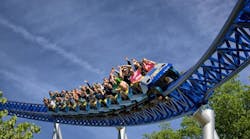
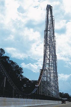
Officials at Cedar Point use words such as tallest, fastest, and steepest to describe their newest roller coaster, Millennium Force. And no wonder. With its 300-ft drop, 92-mph top speed, and 80° slope, it certainly is a record breaker. In fact, Cedar Point officials mention at least ten roller coaster records shattered by the Millennium Force.
But even before riders board the Millennium Force, pneumatics is at work expediting the loading and unloading of passengers. The Millennium Force routinely operates with three trains — each train carries as many as 36 people — and can bring thrills to approximately 1600 riders per hour.
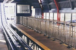
When a coaster train arrives at the loading station, 18 pairs of closed gates keep riders a safe distance away from the track. At the appropriate time, pneumatic cylinders open all the gates simultaneously, and riders climb into the train. The gates are opened by two 2-in. bore, 12-in. stroke air cylinders. The cylinders are connected to a mechanical linkage that opens all 18 pairs of gates simultaneously — one cylinder opens the left-hand gates, the other opens the right-hand gates.
Pneumatics allows regulating opening and closing speed independently through flow-control valves. Also, opening and closing torque is controlled through a pressure regulator. Precise control of pressure provides enough torque to actuate the gates, but a relatively low operating pressure — coupled with air’s compressibility — provides enough “give” to open and close the gates gently and safely.
Naturally, the faster a coaster goes, the tougher it can be to stop. The challenge becomes how to stop it quickly, smoothly, and reliably. Traditional methods of using high-friction pads just won’t cut it. Instead, the Millennium Force is brought to a halt by permanent magnets.
Tim Smith, logistics supervisor at Cedar Point, explains that fins on both sides of a coaster train pass through a series of permanent magnets as the train approaches the unloading station. These magnets are mounted on both sides of the track, and magnetic fields act on the fins to slow down the train. “The faster the train is moving, the stronger the deceleration force imposed by the magnetic fields,” says Smith. “It’s like moving your hand through water: that faster you try to move your hand, the greater the resistance from the water. But if you move your hand slowly, you’ll feel very little resistance. This is how the electromagnets work. Trains entering the braking section at different speeds and with different loads will exit at roughly the same speed.”
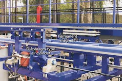
The train then coasts to a second set of magnets that bring it to a halt. These magnets are strong enough to hold the train in place, but because they are permanent magnets, they must be removed to allow the empty train to move forward to the loading station. Again, pneumatic technology answers the call. In this case, once all passengers have exited the unloading area, an operator energizes a set of pneumatic cylinders that moves the magnets away from the train. This allows it to move forward to the loading station.
Smith points out that these are diaphragm-type cylinders. “The rod of each cylinder is attached to a diaphragm, rather than to a sliding piston. It’s the same type of cylinder used in truck brakes. It has no piston rings to wear out or leak, and is virtually maintenance free.”
In addition, pneumatics is used indirectly for the passenger restraint system. Passengers are restrained by a seat belt and cushioned lap bar. This lap bar is held in place mechanically and released electrically. When a train enters the loading-unloading station, a pair of pneumatic cylinders raises a pair of contacts that completes a circuit to release the restraint system. Before the train leaves the loading-unloading station, the cylinders retract to break the circuit, thereby locking the restraints in place. Each train also has a mechanical override to release the restraint system in the unlikely event of a power failure or other type emergency.
Smith says, “Everything on this attraction is designed to be fail-safe. But what’s nice about having pneumatics running so many systems is that the power from the compressed air stored in the system allows us to operate for several cycles even if electrical power has not been restored. The permanent magnets themselves, of course, require no external power of any kind.”
The world’s largest rodless cylinders?
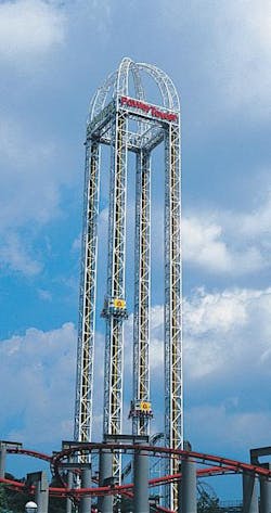
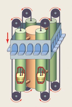
They just may be. But officials at Cedar Point prefer to point out the fun, thrills, and excitement guests enjoy when riding the Power Tower. Power Tower consists of four 240-ft tubes that accelerate a carriage containing up to 12 riders to 50 mph in.3 sec. Each tube is part of a cable cylinder. A cable attached to both sides of a piston inside the tube runs through the center of the tube, exits through the center of each end, then wraps half-way around a pulley at each end. From the pulley, the cable runs parallel to the tube OD, and its ends attach to the top and bottom of the load carriage.
Because of the cable arrangement, routing compressed air to the top of the tube pushes the piston down, thereby pulling the carriage up. Likewise, routing air into the bottom of the tube raises the piston, moving the carriage down. Power Tower actually consists of two separate towers — one uses compressed air to propel the carriage upward from near-ground level. The other uses compressed air to transport the carriage to the top of the tower, then a charge of air propels the carriage downward.
Air for each of the four tubes is stored in a huge receiver mounted centrally among the four tubes. Once riders are secured in their seats, a charge of compressed air first propels the carriage upward. It then is allowed to freefall, which compresses a measured quantity of air in the top portion of the four tubes. Pressure transducers in the tubes communicate to the ride computer how much pressure the loaded carriage exerts on the charge of air. The computer uses this pressure value to calculate the weight of the carriage with its occupants. Next, air is released from the tops of the tubes, and the carriage returns to earth. From the weight calculation, the computer then meters out the precise amount of compressed air to propel the carriage up or down and to cushion the carriage when it approaches the top or bottom of its travel.
When the four tubes approach the end of their stroke, their pistons begin compressing the air that has been metered into the tubes. This causes the carriage to bounce several times as the air is released from the tubes to allow the carriage to gently return to earth. Power Tower contains a total of eight tubes approximately 240-ft long and with diameters of about 8 in. Plus, two 240-ft central receivers each have a diameter of approximately 16 in., so you might expect this attraction to consume huge quantities of compressed air. It does. Power Tower gets its pneumatic power from three 200-hp rotary screw compressors. (A fourth is used for standby operation.) Each is set at an operating pressure of 125 psi and can deliver 990 cfm of air. Each compressor has its own refrigerated dryer.
Hydraulics helps entertain across the pond
Most Americans who are in regular contact with residents of the U.K. will attest to the British as having an offbeat sense of humor. Most British, however, probably feel that the reverse is true. But playing on the British sense of humor is the essence of a new section at Chessington World of Adventures, a theme park on the outskirts of London. As with other major parks of this size, specific areas cater to a certain theme. The new section that opened earlier this year is Beanoland, modeled after the popular, long-running British comic strip featuring Dennis the Menace, Gnasher, and other colorful characters.
One of the attractions at Beanoland is a stunt show where Dennis gets into trouble while trying to pull a prank by altering the ornamentation of a decorative fountain. Renaissance Entertainment, Orlando, produced the show, and Integrity Attractions, also in Orlando, designed and built a fountain lift system and controls for the attraction as a subcontractor to Renaissance.
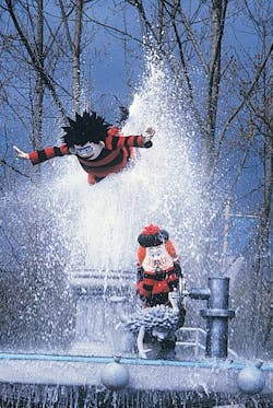
In the show, Dennis and a friend decide to perform some harmless vandalism on a nearby fountain. Dennis uses a ladder to climb into the fountain, then attempts to remove a top piece from it. In doing so, he leans over the center of the fountain, and his friend pulls a prank of his own by opening the fountain’s main valve. Intending to drench Dennis, the friend gets more than he bargained for when a powerful geyser of water shoots upward from the fountain, taking Dennis with it. This cascade of water keeps Dennis elevated high above the fountain, much to the surprise of Dennis’ friend. Or so it seems.
The geyser of water shooting upward appears to push Dennis high above the fountain. Matt Lenz, president of Integrity Attractions, reveals that in reality, a hydraulic cylinder located in the center of the cascading water pushes the character upward. “Because it is completely surrounded by water, and is roughly the same color as the water, the piston rod cannot be seen by the audience.”
Lenz continues, “The Dennis character wears a harness under his costume. The harness supports a lock that mates with another lock on the end of the piston rod. Of course, none of this hardware can be seen by the audience. When the Dennis character leans over the fountain, he very subtly locks himself to the end of the retracted piston rod. Once Dennis is locked into place, an off-stage operator actuates a control that starts the flow of water from the fountain while the piston rod begins extending.
“Pure water is used as the hydraulic fluid to actuate the cylinder — the same water used in the fountain. The top of the fountain has eight nozzles that shoot water into the air. Diffusers on all the nozzles aerate the water so it forms a curtain of spray that hides the piston rod.
“The cylinder itself has a 10-in. bore, 6-in. diameter rod, 78-in. stroke, and is constructed entirely of corrosion-resistant materials. For example, the piston rod is made of 6-in. stainless steel tube, the piston is made of UHMW composite, and the cylinder barrel is made of aluminum tubing. To keep the piston rod properly aligned, the piston is approximately 2-ft long. It’s actually two discs of UHMW composite with a section of 10-in pipe in between joining them. This keeps the rod aligned with the cylinder barrel and prevents binding that might otherwise result from side load caused by movement of the Dennis character.
“Because it is not as strong as steel, aluminum tubing generally is not used for hydraulic cylinders. But we operate the cylinder at a low pressure, so aluminum tubing has more than enough strength. The cylinder only has to lift one person, all the rigging, and the weight of the piston rod. So with a piston area of almost 80 sq in., the pump doesn’t need to develop high pressure. However, because the cylinder has to go from fully retracted to fully extended in only a few seconds, the pump does have to deliver high volume. With a 10-in. bore and 78-in. stroke, the pump has to move more than 5600 in.3 of water in under 5 sec. That’s over 300 gpm!”
The cylinder is double-acting, with meter-out flow control for rod extension and retraction. Cylinder direction is controlled by 6-in. butterfly valves, actuated pneumatically. As with many conventional water hydraulic systems, using a group of digital type valves proves more practical than using a single, very large spool-type valve.
Lenz explained that the current setup didn’t necessarily require a double-acting cylinder. However, as constructed, the system is versatile enough to accommodate adjustments or changes that may be necessary later. “We could’ve saved some money by building a single-acting cylinder, letting gravity retract the rod, and metering the water flowing out of the bottom (cap end) of the cylinder. The problem is, gravity limits retraction dynamics, which restricts what you can do.
“But I learned years ago that in this business, you’ll eventually need to make modifications to just about any system down the road. It’s almost inevitable. The system we designed and built meets the design requirements established early on. But if the show producers want to add a little pizzazz later on, they’ll be able to, simply by reprogramming the PLC.”
Lenz refers to a programmable logic controller (PLC) that operates everything in proper sequence and continually monitors key operating and safety functions. Lenz continues, “Everything is designed with double redundancy for safety, including the controls. That way, an operator can”t accidentally cause something to occur out of sequence; he or she has to use two hands to communicate a command to the PLC. The one exception to this are the emergency stop buttons.”
Considering all this behind-the-scenes engineering, Dennis is really pulling a prank on the audience: probably none of them realize that Dennis is held airborne not by a jet of water, but by a hydraulic cylinder.
Hydraulics reaches the far east
Turning our attention to the other side of the world brings us to Phuket FantaSea, a cultural theme park located at Kamal Bay on Phuket Island, Thailand. This 140-acre theme park comes alive at night by combining the charm and beauty of Thailand and ancient Thai traditions with modern technology and special effects. The result is a stunning theme complex packed with a multitude of activities. The highlight is a Las Vegas-style theatrical show, where state-of-the-art technology and special effects enhance the grace and beauty of Thailand’s myths, mysteries and magic.
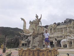
This show, Fantasy of the Kingdom, centers around a centuries-old legend of an enchanted kingdom blessed with unsurpassed beauty, bounty, its joyful people, and their young ruler, the Kamala Boy, riding on his heavenly elephant. To help entice visitors into the show, a statue of the Kamal Boy atop the heavenly elephant seems to come to life. The elephant’s tail, head, ears, leg, and trunk all move, as do the boy’s head and right arm. These movements — 13 degrees of motion — all are synchronized with a sound track to give viewers a sampling of the techno-magic awaiting them inside.
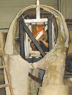
The statue is made primarily of fiberglass cast from sculptures of the elephant and boy. Joints and sections that move are made of silicone colored and textured to closely match color and texture of the fiberglass sections. Inside the figures are hydraulic cylinders that produce motion. A programmable logic controller (PLC) mounted in the elephant’s abdomen controls all motion sequences, and critical motions are controlled by electronic servovalve drivers.
The elephant executes seven degrees of motion: head up and down, head left and right, ears out and in, trunk up and down, tail back and forth, and front-left foot up and down (which involves bending upward at the shoulder and downward at the knee). The combined motions of the trunk and leg allow the elephant to “salute” the viewers.
Meanwhile, the boy’s motions encompass head up-down, head left-right, mouth open-close, and two motions for raising the left arm by bending at the shoulder and elbow. Eleven of the 13 motions are accomplished with double-acting hydraulic cylinders actuating on pivot points. None has a bore greater than 2 in., and operating pressure is about 2000 psi. Left-right motion of the boy’s head is accomplished with a rotary actuator. (The rotary actuator is used because the 120° arc of motion would not be practical with a cylinder.)
The articulated statue stands atop a pedestal as part of a display fountain, which is directly over a small basement housing the hydraulic power unit. The platform on which the figure stands pivots 90° clockwise and 90° counter-clockwise from center to provide a clear view to all watching this pre-show. The motion is achieved with a hydraulic motor driving a chain attached to the platform.
Lenz explains, “It would’ve been nice to turn the statue left and right through a rotary actuator mounted right under the center of the platform. But this space near the center of the vertical axis must be used for routing fluid and electrical lines from the stationary HPU and base to the rotating members. Instead, we made a cylindrical extension attached to the underside of the platform that acts as a big sprocket. We then attached a length of roller chain to this extension and drive it with a hydraulic motor. The motor is mounted vertically, so the chain drive runs parallel to the ground. If the statue rotated continuously, we would’ve had to route hydraulic lines through a rotating union. But because it has a total rotation of only about 180°, we were able to accommodate the movement simply by making the hoses long enough and managing the movement of their bending.
“To keep hoses from binding or getting tangled, we bundle them together, place the assembly loosely in a sleeve, and gently bend the assembly into an S curve to provide plenty of slack for movement. We also placed a tray made of UHMW plastic to keep the hose and cable assembly from rubbing against anything that could otherwise cause premature wear of the hose cover.”
Another design challenge was to make the trunk’s movements look natural. One method could have been to mount a cylinder at each pivot point of the trunk frame structure, but this would have been expensive, space restrictions would have made it impractical, and it wasn’t necessary because the natural movement on an elephant’s trunk is for the joints to move in sequence. Another alternative would have been to string a cable through each of the joints and use a cylinder to pull on the cable to move the trunk and have it return by spring force or gravity. This option, however, would have made it difficult to achieve natural movements because motion would have been difficult to control when retracting the cylinder. It also would have been cumbersome to design and build.
Instead, Lenz decided to build a trunk structure with joints linked together so all move simultaneously, but not necessarily at the same rate or even in the same direction. As a result, as the cylinder extends, the trunk gradually curves upward, but the end portion of the trunk curves outward. When the cylinder retracts, the trunk relaxes and moves naturally back toward the ground.
Pneumatics for safety
Lenz explained how it is important to recognize which type of technology is most suitable for an application. For example, inside the theater for the Fantasy of the Kingdom show, his company designed and built what he considers the second-largest stage lift in the world. “The largest stage lift in the world is at Radio City Music Hall in New York. That one is hydraulic. The lift we built is electromechanical, not hydraulic. So ours is the largest electromechanical stage lift in the world. It can handle payloads to 120 tons; it is 50-ft wide, 40-ft deep, and has a maximum vertical lift of 28 ft. We couldn’t use hydraulics because the high water table on the island made it impractical to dig deep pits to house cylinders under the stage.”
Even though it is not powered by hydraulics, the stage lift has a sophisticated triple-redundant safety system that makes extensive use of pneumatics. Lenz continues, "First, we have a pair of Powr-Tube flexible-wall cylinders at each end of the stage that, when pressurized, create an interference fit between the movable stage and massive concrete foundation surrounding it. These cylinders are look like 6-ft sections of fire hose crimped at each end with a steel flange. The relaxed tube is flat, but pressurizing it causes it to expand radially and exert tremendous forces between the stage and foundation. Friction pads mounted between the tubes and foundation make the brakes hold tight.
“Second, four of the eight gearmotors have a Horton air brake mounted between the motor and gearbox. These are spring-applied, pressure-released brakes, so if a power failure occurs, the gearmotors will not turn.
“Third, we use pneumatic cylinders to lock the stage in place when it is in the full-up or full-down position. We built eight sliding I-beams into each side of the stage that fit into pilot holes cast into the foundation. Each I-beam is 4-ft long and slides into and out of its respective pilot hole by way of a pneumatic cylinder. They work just like deadbolts. Limit switches communicate signals to the stage PLC when all cylinders are fully extended or fully retracted. Unless all cylinders are fully retracted, the PLC will not release pressure from the shoe brakes or release the brakes on the gearmotors.”
