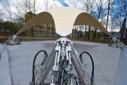
When we hear of hydraulic simulation, most of us think of motion simulators, where a multi-axial motion base moves in multiple directions to simulate aircraft flight or applications involving highly dynamic motion. However, a motion base was designed and built earlier this year to simulate wind snow masses, and other extreme weather conditions.
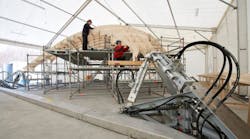
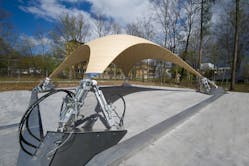
Maximum load capacity with minimal consumption of materials — this is how supporting structures in construction should be today. Researchers from the University of Stuttgart and Bosch Rexroth AG, Lohr am Mein, Germany, have now come a great deal closer to achieving this goal. They have constructed a wooden shell that is much thinner than anything deemed possible — until now. With a mere 4 cm thickness, the shell spans a surface of over 100 m2. The structure is situated on the Vaihingen Campus of the University of Stuttgart and was introduced to the public on April 16, 2012. The extreme slimness of the shell is made possible by using an adaptive structure.
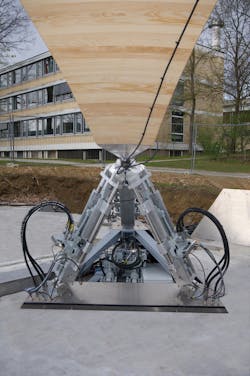
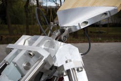
Structures had always been designed for an exact maximum stress. This type of stress, however, generally only occurs very rarely — and only for a short time. Therefore, most building materials used today serve these peak loads that rarely occur. The aim of ultra lightweight structures developed at the University of Stuttgart is to achieve a drastic saving of materials and a better reaction to dynamic loads through an active manipulation of the structure. In the case of the Stuttgart wooden shell, this manipulation is achieved through hydraulic drives. Each drive rests on the points of support of the shell and generates movements that compensates for deformations and material stresses caused by wind, snow, and other loads.
The shell is made of wood and supported at four points. Three of these points can be moved individually by hydraulic cylinders and freely positioned in space. Sensors monitor the load status at numerous points on the structure. Targeted movements support points react to variable loads — for example, heavy snow accumulation. The reactive motions, therefore, reduce deformations and material stresses. Compared to conventional, passive structures, this considerably reduces the amount of material needed for the shell. The load balancing takes place through a Rexroth control system, which was developed specifically for hydraulic drives. The core task of the control system is to implement the complex hydraulic control tasks of the shell structure so that the support structure can react to a change in the load status within milliseconds.
Active vibration damping and adaptation to changing loads can be applied to many areas of construction: stadium roofs, high-rise buildings, in wide-spanning façade constructions, and bridges. The results of the research project enable a completely new construction method that not only saves resources, but substantially increases the performance of supporting structures as well. Not only that, but lighter structure itself reduces the weight that must be supported by underlying structures and also reduces material fatigue and damage to the structure.
In order to be able to actively compensate loads and vibrations, appropriate factors must be precisely recorded and predicted. A subsequent step would be to calculate the necessary counter-movements in real time and precisely implemented through the hydraulics. Researchers from the University of Stuttgart developed simulation models for this purpose, which led to exact prediction of the behavior of the structure. Therefore, material stress and vibration behavior under static and dynamic conditions are taken into account.
The scientific foundations for the project were constructed at the Institute for Lightweight Structures and Conceptual Design (ILEK) and at Institute for System Dynamics (ISYS). Bosch Rexroth supplied the active elements of the prototype. With cooperation from the University of Stuttgart, Bosch Rexroth took over project management, selection and design of the hydraulics, and commissioning.
The large-scale adaptive structure is the result in a joint effort between the Institute for Lightweight Structures and Conceptual Design (ILEK) and Institute for System Dynamics (ISYS) at the University of Stuttgart, and with the cooperation with Bosch Rexroth. The project was also supported by Sensor-Technik Wiedemann GmbH, Eschenbach Zeltbau GmbH & Co. KG, Wilhelm Gerüstbau GmbH, Ulrich Lübbert Warenhandel GmbH & Co. KG, Friedrich Wahl GmbH & Co. KG, Leitz GmbH & Co. KG, and Rütgers Organics GmbH.
For more information about ILEK visit www.uni-stuttgart.de/ilek, ISYS visit www.isys.uni-stuttgart.de, and Bosch Rexroth at www.boschrexroth.de.
