This file type includes high resolution graphics and schematics when applicable.
As demand grows for finer control and functionality, especially in the heavy industry, subsea, and mobile equipment worlds, users and systems integrators rely more heavily on sensor-instrumented hydraulic cylinders. Ultimately, one must determine the application’s requirements and the technology that best suits it on a total installed cost versus performance basis.
Populating these cylinders are position feedback sensors, which employ one of three traditional technologies: magnetostrictive, variable resistance, and variable inductance sensors. Other sensor technologies have seen some success in this application, but the focus of this article is to compare these three most popular technologies.
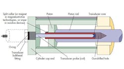
Incorporating these sensors into a cylinder typically involves the use of a long probe that extends into a deep, small-diameter blind hole drilled into the internal end of the cylinder rod. This process is often called gun drilling, due to its resemblance to a gun barrel.
A Glance at the Big Three
Magnetostrictive technology has been the preferred technology for high-accuracy applications. The sensor incorporates a stainless-steel tubular probe and a short toroidal permanent magnet, which is installed in a counterbore in the cylinder’s piston. The most common package is designed to thread the sensors’ electronics housing into an O-ring port in the back of a cylinder, with the long, slender probe fitting inside into the rod’s bore.
Magnetostrictive technology uses the “time of flight" principle to determine the magnet's position with high accuracy and moderate response time. The magnet reflects a torsional mechanical pulse, which is transmitted along a wire inside the probe, called a waveguide. Typically, each magnetostrictive-sensor manufacturer has its own style of magnet with proprietary mounting features, such the number of holes, the hole pattern, etc.
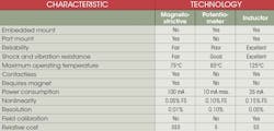
Magnetostrictive sensors can consume a fair amount of power and may not be as mechanically rugged as the other two main sensor types. They offer high electrical performance, and the magnetostrictive sensor's package design is tailor-made for port-mounted in-cylinder use.
Variable-resistance (potentiometer-type) sensors, commonly called pots, are selected when purchase cost becomes more of a driving factor than high accuracy. A resistance pot is usually embedded into the cylinder's cap end plate, as opposed to the port mounting of magnetostrictive sensors. It uses an insulated round carrier, which is attached to the internal end of the gun-drilled cylinder rod, and supports an electrically conductive wiper that contacts the surface of a partially conductive plastic probe. As the wiper moves along this plastic element, its resistance changes in a linear fashion, making it fairly easy to determine the carrier's position and, thus, the rod's position.
Resistance pots have been widely used for position measurement in cylinders because of their ruggedness, favorable stroke-to-length ratio, and strong analog dc voltage output, which is a percentage of the input voltage. The major drawback to resistance pots is they undergo wear, which limits service life. This is especially true if the cylinder is actuated at a high frequency, or even more importantly, dithered over a short range to improve a system's dynamic characteristics. Because a resistance pot is embedded into the cylinder, replacement of a worn-out pot can be time-consuming and expensive, and may even necessitate replacing the entire cylinder.
Although variable-inductance position sensors have seen use in cylinders, they don’t have the widespread recognition of magnetostrictive sensors or resistance pots. The non-contacting technology of variable inductance holds significant advantages over resistance potentiometers regarding product life and long-term reliability. Furthermore, variable-inductance sensors usually can compare favorably to the performance of magnetostrictive sensors in terms of linearity, resolution, and frequency response, but at lower cost. Equally important is the fact that variable-inductance sensors can withstand much greater shocks and vibration, such as those commonly found in heavy-industrial and mobile-equipment applications.
This file type includes high resolution graphics and schematics when applicable.
More on Variable Inductance
This file type includes high resolution graphics and schematics when applicable.
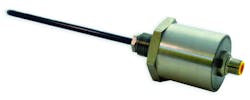
Linear variable-inductance sensors cover the middle ground between the higher level of performance and external-port mounting flexibility associated with magnetostrictive sensors, and the ruggedness and price of an embedded resistance potentiometer. Inductance sensors operate by measuring the resonant frequency of an oscillator circuit that uses an inductive probe whose inductance is varied by the position of the gun-drilled rod over it. They typically feature full-scale ranges of 4 in. (100 mm) to 36 in. (900 mm), and come in both port-mounted and embedded packages with connector and cable terminations that match those found on most catalog magnetostrictive sensors.
Inductive sensors are specified with either analog dc voltage or current output; an SSI digital output is available for OEM applications. The variable-inductance sensor’s non-contacting solution does not require a ring magnet. Furthermore, if it’s specified to replace an existing magnetostrictive sensor, the magnet required by the magnetostrictive device can be left in place and will not interfere with the replacement sensor’s basic operation.
Many variable-inductance sensors offer remote field calibration. This feature lets a user scale the sensor’s output while it’s being installed on the cylinder, without having to scale the unit in an operating control system. Pushing a button sets the zero and the full-scale output points, so the sensor will provide the desired full-scale output over its newly set range.
Requirements for instrumented cylinders earmarked for subsea applications have dramatically increased in recent years. On that front, pressure-sealed versions of variable-inductance sensors allow users to install the sensor/cylinder in a subsea environment in ocean depths to 10,000 ft. (3,000 m) with 3,000 psig of internal hydraulic pressure.
Although many hydraulic cylinder applications may be best served by resistance potentiometers or magnetostrictive sensors, these applications tend to fall to either side of a bell curve. Recent electronic advances and the flexibility of package designs make variable-inductance sensors cost-effective alternatives for mainstream in-cylinder applications that exist closer to the peak of that bell curve.
Edward E. Herceg, Chief Technology Officer
Alliance Sensors Group, a division of H.G. Schaevitz LLC, Moorestown, N.J., (856) 727-0250
This file type includes high resolution graphics and schematics when applicable.
