When the 2017 NFL season begins, Minnesota Vikings fans will enter the $975 million U.S. Bank Stadium through the five largest pivoting glass doors in the world. The stadium’s entryway is considered one of the most impressive kinetic structures of its kind. Each door is opened and closed by three pairs of 8-in. bore hydraulic cylinders. They stand 75- to 95-ft. tall, are 55 ft. wide, and weigh 57,000 lb. each. Aesthetically, the structure provides fans with an “open-air” experience even from inside the stadium.
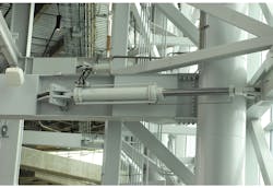
U. S. Bank Stadium uses 15 pairs of hydraulic cylinders to open and close the five largest pivoting glass doors in the world. The hydraulic system safely and reliably actuates the doors and has been designed to blend in with the building’s architecture, providing fans with an “open-air” experience from inside the stadium. (Photo courtesy of Associated Press)
However, maintaining this critical effect, while properly actuating the doors, was a complex challenge. Issues related to space usage, fluid transfer, controlling door movement, cost management, and others necessitated a solution that was compact, inconspicuous, and economical. The result is a custom regenerative hydraulic system that provides the necessary efficiencies and cost savings over a traditional equal-area circuit design.
Standard or Regen?
In a basic hydraulic system using a single cylinder, a directional valve routes fluid from its A port into the cap end of a cylinder to push a door open around a hinge. At the same time, fluid from the cylinder’s rod end flows into the valve’s B port and back to tank with minimal backpressure.
However, when a pair of cylinders is used, the push and pull requirements add complexity because pressure and flow requirements at the rod end of one cylinder are different from those at the cap end of the other. This is because the piston rod’s volume uses space that otherwise would contain fluid. The rod end also has a smaller effective piston surface area. This complicates using a pair of cylinders to actuate a door because fluid pumped into the cap end of the extending cylinder must be at a greater flow rate than fluid pumped into the rod end of the retracting cylinder. The force difference between the two cylinders (in this case, the extending cylinder would transmit greater force than the retracting cylinder) also presents a challenge.
Advantages of Regeneration
To address this complexity, a pair of cylinders in a push-pull arrangement was modified by adding a continuous regeneration function using a 4-check cushion-lock circuit from Sun Hydraulics Corp. The regeneration function is provided by the extending cylinder within the pair.
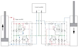
Each of five regeneration manifolds has a cross-piloting circuit that allows the pressure from the incoming oil to open a counterbalance valve and route (regenerate) fluid from the cylinder’s rod end fluid directly back into its cap end.
The cross-piloting circuit allows the pressure from the incoming oil to open the counterbalance valve and route (regenerate) fluid from the cylinder’s rod end directly back into its cap end. This fluid does not go back to tank; not yet, anyway. The same pressure feed for the cap end of the extending cylinder is teed into the pressure feed for the opposing (retracting) cylinder’s rod end. When the opposing rod end is pressurized, the same pressure is cross-piloted to the cap-end counterbalance valve. Flow from the cap end now goes straight to tank through the dedicated tank line.
As a result, each time fluid from the cap end of either cylinder is flushed to tank, the purge of oil is complete. An advantage of the cylinder control manifold circuit is that all cylinder work line oil flows are one-way, non-reversing. The return oil from each cylinder flows through a tank return line connected to each cylinder control manifold. Excess fluid from the non-regenerating cylinder flows through the counterbalance valve when pressure is applied and back to tank through the dedicated tank line. This allows a continuous flushing from cylinder to tank, so oil is always filtered.
The makeup oil from the reservoir is almost identical to volume from the rod end of the opposing cylinder, which compensates for the difference between the cap- and rod-end volumes. In addition, this equal area oil exchange and regeneration circuit allows for an extremely small reservoir compared to a conventional circuit. This addressed the application’s important need to reduce space. By regenerating and also providing almost the same differential volume for the cap end as rod-end volume of the same cylinder, the close balance of oil prevents the huge flow of oil back to tank that would occur in a conventional design. This significant flow efficiency advantage results in a 100-gal reservoir instead of one requiring 650 gal or more for the entire system of 30 cylinders.
The Cushion-Lock Manifolds
The cylinder cushion-lock manifolds are directly connected to the cap-end block using a Code 62 (6,000 psi) 4-bolt flange port, with steel tubing run to the cylinder rod-end port. Each cylinder-mounted manifold also has two normally closed needle valves, which can be opened to float the cylinder for installation, flushing, testing, or maintenance.
Implementing a direct-mounted and hard-piped solution provides critical benefits for controlling each door. If any work lines from the reservoir or control valves break, leak, or become damaged, the doors will remain locked and controlled. This eliminates risks posed by hoses, which can be cut, wear out, or rupture, resulting in a loss of control of the door.
Three pairs of 8-in. bore cylinders open and close each door. A manifold connected to the cap end of each cylinder not only provides several functional benefits, but adds to aesthetics by not standing out visually.
The design also prevents wind from overrunning the door in either direction. Because of the stadium’s location in a high-wind zone, this advantage was vital to system integrity. If excessive wind pushes on the door, the counterbalance valve will lose pilot pressure and smoothly lock the door in place.
Finally, removing air pressure from the work lines is solved through the design of this system. The cylinder work lines are quite long, so the regenerative approach eliminates what would otherwise be a difficult and time-consuming process to purge air from the cylinders and work lines. The circuit continuously purges itself as it operates.
Details on Components
In addition to the small volume of the reservoir, this application also conserves space by making extensive use of hydraulic integrated circuits: multiple cartridge valves mounted in custom manifolds that consume a fraction of the space of conventional, line-mounted components.
The 4-port counterbalance valves were used on the cylinder rod-end ports because the regen circuit places backpressure on the manifold’s cavity Port 2. Normally, this pressure would affect the valve’s pressure setting, which is typical for regen circuits that require load holding in the cylinder extend direction. However, backpressure at Port 2 on this valve does not affect the valve setting because the spring chamber is vented.
The Sun CWCL valves were used because they have a 2:1 pilot ratio, which makes the circuit stable. Sun documentation explains: “Vented counterbalance valves with pilot assist are meant to control an over-running load. The check valve allows free flow from the directional valve (Port 2) to the load (Port 1) while a direct-acting, pilot-assisted relief valve controls flow from Port 1 to Port 2. A pilot-assist feature at Port 3 reduces the effective setting of the relief valve at a rate determined by the pilot ratio.” The cylinder cap-end ports are controlled by a Sun CBBA valve, a restrictive 3-port counterbalance valve selected for circuit stability at the lower flow rates.
The five-cylinder control manifolds use standard NG6 4/3 proportional directional valves with integral electronics from Atos North America. The integral onboard electronics help in setup and reduce extra control hardware and programming. This is because the valve’s electronics can be independently programmed to adjust the control and reaction of the valves without external controls—all they need is a standard analog or digital input signal.
The manifolds on the cylinders do all the cylinder control, so the 4/3 proportional directional valve only meters oil into the door cylinders to move them. No return flow goes through the 4/3 directional valve. As already discussed, this feature promotes fluid cleanliness and self-purging of air. The control manifolds’ 4/3 proportional directional valves are pressure compensated using Sun’s direct-acting PRDR pressure-reducing valves to function as adjustable load-sense modulating cartridge valves.
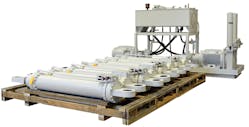
This hydraulic power unit and bank of cylinders will be installed at U.S. Bank Stadium for opening and closing five massive glass doors. Because the HPU will be installed in a remote location, the doors will move with little noise.
The application requires each door’s directional-control circuit to provide proportional pressure cutoff, which is achieved in the control manifolds using Atos RZMO NG6 proportional relief valves as remotely controlled load-sense pressure limiters on the Sun PRDR modulating valves. The Atos proportional valves were used because the customer required industrial-type (6-pin connecting plug) valve electronics. Furthermore, the NG6 (D03) manifold interface pattern allows revising the control manifold circuit if necessary.
Like Nothing You’ve Experienced
In the end, the engineers solved the many challenges of operating the 40,000-ton glass doors smoothly. By using a custom-designed cushion-lock regeneration circuit design, the issues of minimizing space usage, fluid transfer management, controlling door movement, and keeping costs down were achieved, enabling the Minnesota Vikings organization to create what is considered one of the greatest stadium designs in American sports.
John White, Kevin D. Close, and Dave Keen are with Advanced Fluid Systems Inc., York, Pa. For more information, call (800) 220-1014, or visit the company's site.
