Hydraulic capacitance and dead time are related because they are affected by mounting the valve away from the cylinder. Hydraulic capacitance refers to the compressibility of hydraulic lines. This capacitance is usually neglected in most mobile and general industrial hydraulic systems. But hydraulic capacitance should not be ignored in high-performance hydraulic systems using closed-loop control. Dead time, on the other hand, is the time it takes the actuator to start to move after a control signal or action is taken. When a valve spool moves, it changes the pressure downstream, but the pressure wave does not travel instantaneously. It travels at the speed of sound in oil.
In general, it is best to mount servovalves on the cylinder whenever possible, or at least as close to the cylinder as possible. Mounting the valve on the cylinder maximizes the natural frequency of the system by reducing the system’s capacitance and dead time. The terms capacitance and dead time are not usually mentioned when talking about hydraulics, but minimizing both effects is crucial for best hydraulic servo control.
Hydraulic capacitance is expressed as the change in volume divided by the change in pressure. It is important to realize that more than just the oil has capacitance. Hose, piping, and the cylinders themselves have capacitance, too. However, I have done some calculations on the capacitance of metal piping and cylinders and have found it so be so small that it can be ignored. That leaves the capacitance of the oil, hose and the accumulator. The accumulator is specifically intended to have capacitance. Accumulators are placed between the hydraulic pump and the control valve and should allow the volume of oil in the system to change with little change in system pressure.
If the valve is mounted on the cylinder, then only the capacitance of the trapped volume of oil between the valve and the piston needs to be considered. However, if there is hose between the valve and the cylinder’s piston, then the capacitance of both the hose and the oil must be considered.
The formula for hydraulic capacitance is
Where:
CH is the hydraulic capacitance.
V is the volume of oil being compressed.
Β is the bulk modulus, which is about 200,000 psi (1.35x10⁹ Pa) for oil. Bulk modulus is a measure of a fluid’s resistance to compression. The higher a fluid’s bulk modulus, the lower its capacitance.
The formula for the cylinder’s natural frequency considers the bulk modulus of oil and the volume of trapped oil between the valve and the piston. The simplified formula for estimating the natural frequency is:
Where
ωn is the natural frequency in radians per second. (Divide by 2π to get frequency.)
Aavg2 is the average area of both sides of the piston.
m is the mass of the cylinder and load.
V is the trapped volume of oil between the servo valve and piston.
This formula can be written combining the bulk modulus of oil and cylinder volume into a single formula using a capacitance term.
The capacitance will be increased with the capacitance of a hose, if any. In the above equation, the H subscript represents the capacitance of the oil. In the following equation, the h subscript represents the capacitance of the oil. Computing the hose capacitance is difficult because little or no data is available about the capacitance of hydraulic hose.
As noted, before, the capacitance of hose can be estimated as the change in volume divided by the change in pressure. Calculating the capacitance may be more accurate this way because the change in volume with a change in pressure may not be linear.
Data on the hydraulic capacitance of hose cannot be found on the internet. If there were data, they would need a specification of capacitance per unit of length to let users multiply this number by the length of hose between the valve and the cylinder. If hydraulic hose must be used after the valve, you can only try to keep it as short as possible and hope it doesn’t affect the capacitance too much. The extra capacitance will reduce the natural frequency even more because the hose capacitance, Ch, is added to the denominator of the formula for natural frequency
Adding piping—especially hose—between the valve and the cylinder degrades the performance of servo hydraulic systems by reducing the natural frequency, which also limits the frequency of motion of the hydraulic servo actuator. However, there is another detrimental effect: dead time.
Again, dead time is the time it takes the cylinder to begin moving after a control signal or action is taken. Movement of the control valve’s spool changes the downstream pressure, which travels at the speed of sound in oil.
The speed of sound in oil is about 1.2 m/msec, or about 4 ft/msec. This means the pressure waves in oil take time to travel from the valve to the piston. It also means it takes time for pressure waves to reach pressure sensors. This is another reason why it is vital to mount valves and pressure sensors as close to the cylinder as possible to reduce control delays. You’d need a really advanced motion controller to deal with such a system. In this case, it takes about 10 msec for the pressure changes at the valve to reach the piston. Compensating for these delays is difficult because it requires a precise model of the system, the control algorithm becomes more complicated, and more processing power is required.
Dead time has always been a problem in process control because the systems are so big that it takes time for material and signals to move from one point to another. Those doing hydraulic servo control have been mostly unaware of this problem. It has been known that servo valves should be placed as close to the cylinder for a long time. However, this was done primarily to reduce the trapped volume of oil between the valve and the cylinder, thereby making the natural frequency as high as possible. A high natural frequency allows the velocity of the motion to be higher. However, there is a second reason: to reduce the time it takes pressure waves to travel from the valve to the piston.
The dead time adversely affects motion because the effect of the output due to the feed forward gains (feed forward gains are predictive terms that cause motion to start independent of the amount of error between the current state of the system and the target state) is delayed by the dead time. Closed-loop controller gains must be reduced in this case to keep the motion-control algorithm from overreacting from not receiving any motion feedback. Consequently, the closed-loop gains are not as effective at reducing errors because the effects of the feed forwards are delayed.
There are algorithms that can predict the correct output using a model of the system without the dead time. These algorithms calculate what the current output should be, then compensate later by checking if the system reacted as it was expected to. The algorithms’ predictions are never perfect, but they do reduce following errors. However, this ability comes at a cost of complexity and more computing power.
This all comes back to the simplest solution: Mount the valves and pressure sensors on the cylinders or as close to the cylinders as possible.
High-Tech Doughnut Surfing
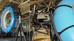
About 10 years ago we participated in the development of a simulated water slide for the Discovery Channel’s program series called “Prototype This”. The water slide is a 30-ft diameter hollow “doughnut” that raises up and down and also tilts as it spins. Riders inside the doughnut surf on a cascade of water that rides along with them.
An issue with this setup is that the designers had 50 ft of hydraulic hose between the control valves and the hydraulic actuators on the structure. The effect of all that hose was to cause the actual cylinder motion to lag behind its target motion due to the expansion and contraction of the hose as the hydraulic fluid ebbed and flowed in the lines. This action made it too difficult to tune a simple PID control algorithm. The designers could have compensated for this by reducing the proportional gain to make the system more sluggish. However, this would not serve the needs of the application. In retrospect, the hydraulic valves should have been mounted directly on the cylinders.
To fix the problem caused by the long hoses, Delta Computer Systems was called in to help with programming the motion controller, and we added a second-derivative gain to the control algorithm. The Delta RMC has an option that supports acceleration control, which works to reduce the error between the actual acceleration of an axis and the target acceleration at a point in time. This results in a speedup or slowdown of an axis’ motion when it starts lagging behind.
To set the value of the acceleration gain, we ran some experiments, trying different values and plotting the results using Delta’s RMCTools software package. When we noticed that the system had become very sensitive to small changes in axis position, we added a filter to the drive output of the motion controller to reduce the noise.
To further ensure that the system would respond quickly to the changing target motion profile, we added a feed-forward term to control algorithm. We tuned all the parameters and watched the graphs produced by RMCTools to see if control was improved. When we were done, the control of the system was “as smooth as silk”.
Peter Nachtwey is president of Delta Computer Systems Inc., Battle Ground, Wash. For more information, visit deltamotion.com.


