This file type includes high-resolution graphics and schematics when applicable.
Pressure regulators take system pressure and reduce it for specific applications. When selecting a pressure regulator, consider the maximum inlet pressure, type of adjustment, reduced secondary pressure, and accuracy.
Most pressure-control regulators feature either a piston or diaphragm control construction and a balanced poppet. Piston regulators are more durable and robust, but are not quite as efficient at holding and maintaining a set downstream pressure. Diaphragm regulators are the most common style and maintain a set pressure within the limits required of most industrial applications.
A third style is available as well, featuring a rolling diaphragm, which can give the long service life of a piston-style unit with the accuracy of the diaphragm units. This design is often used in precision regulators, where compressed air pressure must be precisely controlled for process applications rather than for fluid power.
After establishing the maximum flow, inlet pressure, and secondary pressure required, select the correct regulator based on manufacturers’ performance curves. Note the inlet pressure on which curves are derived because different manufacturers may use different inlet pressures. Many manufacturers have attempted to provide performance curves on an inlet pressure of 100 psi, with set secondary pressures of 90, 75, 60, 45, and 30 psi to make it easier to compare and select products.
Spring into Action
Next, determine the regulator’s adjustment spring range. Regulators come with various spring ranges to offer the user better adjustment and control of the secondary set pressures. A common misconception is that a 60-lb spring can be considered a pressure limiter and will only give a 60 psi output. This is not true, as a 60-lb spring can supply an adjusted pressure of well over 60 psi. A regulator’s pressure-control spring is not a pressure limiter.
When selecting a spring range, choose a control spring that will place the desired set pressure as close as possible to the middle of the control spring’s range. This gives the maximum amount of adjustability and control.
Elements of Style
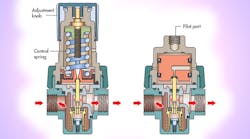
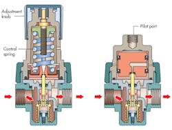
The next choice is to select an adjustment style: manual or pilot-operated, as shown in the illustrations. Manually operated units use a control knob or T-handle to adjust the regulator’s output pressure. The non-rising control knob is the most common style used today because of its compact size and styling. The T-handle version is the more traditional style and is more commonly found on heavy-duty equipment.
A pilot-operated regulator simply replaces the standard control knob and spring with a pilot chamber. A small external regulator supplies a control pressure to the pilot chamber. Because most pilot-operated regulators have a 1:1 ratio of pilot pressure to output pressure, a pilot pressure of 100 psi would deliver 100 psi out of the main regulator.
A standard industrial pressure regulator will have an accuracy of 2 to 4 psi, and if more accurate pressure control is needed, a more precise-design regulator—such as a rolling diaphragm—should be selected. Precision regulators use single- or double-diaphragm chambers and reduced poppet areas to improve performance. Precision regulators typically also have a constant relief bleed to improve the regulator’s ability to relieve excess pressure. It also makes it more accurate, with an accuracy of within 0.05 to 0.5 psi.
Spend Money to Save Money
In general, if you reduce a system’s operating pressure by 2 psig, you can save 1% in overall operating cost. This savings can start at the point of use by revisiting your existing applications to reevaluate required pressures with the intent of reducing them.
One of the most common applications where you can realize savings is a standard air cylinder moving a load into position and then resetting itself. Common practice is to operate cylinders at the same pressure for extension and retraction. However, by applying a dual-pressure technique, you save energy by using high pressure only where it is needed.
For example, if high force is needed only for the cylinder extension (push stroke), a dual-pressure regulator can be installed in the line connecting the directional valve to the cylinder’s rod-end port. This configuration will route full pressure to the cap end of the cylinder for extension, but apply a reduced pressure at the rod-end port for retraction. Installing a $50 regulator might save nearly $300 per year.
Not all regulators are capable of this function. Regulators with a piston or a rolling-diaphragm construction tend to perform best because of their long life. However, a common flat-diaphragm regulator (which is susceptible to rupturing from repeated stress) can be used by installing a bypass check valve in parallel to route exhaust flow past the regulator.
Combined Functions
Manufacturers frequently pre-assemble filters and regulators to form combination units. They’re packaged together as common body sizes with common connection port sizes. Modular connections also ease conversion between metric and inch port types. Interconnections may be via threaded nipples or modular face connectors. Modular connectors facilitate component removal for servicing or cleaning. In addition, some manufacturers combine filters and regulators in stacked assemblies where the filter head becomes the regulator body. The components share common inlet and outlet connections, which makes the assembly very compact.
Such packaged units are practical choices for most industrial applications. The selection criteria are the same as with any of the individual components, except that the combined pressure and flow performance becomes the only consideration. When critical requirements dictate the use of specialty filters or precision regulators, the assembly probably must be made up of individual selections and connected with pipe nipples.


