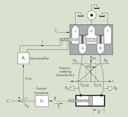
To understand the function of and the need for integral control, you must understand the shortcomings and limitations of the proportional electrohydraulic positioning servomechanism. A simplified, combined cutaway and block diagram is shown in Fig. 1.
1. This simplified cutaway/block diagram shows how pressure metering in the valve combines with disturbances within the valve to generate cylinder positioning error.
Consider that no load is exerted on the cylinder (ƒL = 0). If the cylinder is to be stopped, its rod-end pressure must exceed the cap-end pressure by the amount appropriate for the cylinder's area ratio. Furthermore, there must be enough current into the valve’s solenoid coil to sustain holding pressures in the valve. The holding current is identified in Fig. 1 as IST, NL—the stall current under no-load conditions.
Now let’s apply an external load, which will cause the cap-end pressure to rise. The metering characteristics of the valve demand that the rod-end pressure drops. The new equilibrium conditions are identified as IST, FL, representing stall current under full load. Obviously, this requires a change in coil current by an amount indicated by ∆I.
The current results from the servoloop closure, and assuming no change occurred in command signal C, the new current could result only from a change in the position transducer output, VX. Note that the output of the transducer changes only if the cylinder position changes. We then conclude that the positional servo mechanism—under this proportional control—cannot perfectly compensate for load changes and inherently produces a load-induced positioning error.
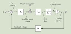
Disturbance forces, FD, which act on the valve spool, yield similar results. By simple analytical processes, all disturbances can be resolved into disturbance currents that act on the valve input. Furthermore, once the loop is designed and gains have been established, the disturbances can be resolved into output positioning errors. The details will not be revisited here, but Fig. 2 summarizes them in schematic form.
2. This block diagram resolves all disturbances into a single disturbance current acting on the valve input current.
Consider that the cylinder is to be stopped: it is in a positional steady state, and the necessary force balance acting on the piston exists. This requires that the velocity be zero. In Fig. 2, this means that the input to the position integrator must be exactly zero. Similarly, the valve output flow must also be zero, so that the effective current into the valve, IEFF, is zero.
An equation that summarizes the steady-state condition at the input to the valve flow gain block, GQ, reflects the effective valve current and is given by:
IEFF = ID+ CA – AHX
But for positional steady state, the effective input current of the valve is zero, so:
XSS = (ID+ CA)/AH
After separating into two terms:
XSS = ID/AH + C/H
This equation is interesting because it shows that in a condition of zero disturbance current, the output position, XSS, is simply the command signal, C, divided by the transducer gain, H, the desired result. But it also describes the effects of disturbance current and clearly shows that the effects of it are reduced inversely proportional to the magnitude, AH. Therefore, even though the disturbances are inevitable, their effects can be held within bounds if the loop gain is high enough.
Indeed, this is a design ploy for systems using proportional control. That is, knowing what load, pressure, and temperature variations to expect, we can match the allowable positioning error to the expected disturbance current and determine the gain and closed-loop bandwidth required.
Reducing the Effects of Disturbances
Now let’s shift our focus to reducing the effects of disturbances that act upon control systems. The effects of these disturbances can be measured. Therefore, at least in principle, they can be corrected; also, in practice, they are correctable—within limits.
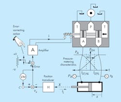
The system of Fig. 3 is the same as that appearing in Fig. 1. However, a human observer armed with an error-correcting potentiometer and voltmeter has been added. When no load was on the cylinder, the system was at null. Therefore, the error-reading voltmeter would have indicated zero. This can be done in a real system by adjusting the null control on the servovalve while observing the voltmeter and continuing to adjust until the voltmeter reads zero.
3. A human observer reading the error voltage on a voltmeter can eliminate, the steady-state positioning error caused by any disturbance.
Now consider that the magnitude of the load increases. For reasons already explained, the cylinder will move to a new position, resulting in a load-induced positioning error. But, more importantly, a readable voltage will appear on the voltmeter. That value, divided by the transducer gain, is the amount of the position error.
If the human observer turns the error-correcting pot while watching the voltmeter and continues adjusting until it reads zero, the cylinder must go back to its original, unloaded position. The load-induced error has been corrected! And if this is done at every stopping point—and if sufficient time exists—all disturbances can be compensated for.
This is the essence of integral control, but this example used a human operator affecting the control. Humans are good at such things. For example, in controlling the speed of a car, if the driver notices that speed is too slow or too fast, he or she increases or decreases power to the engine until achieving the desired speed.
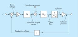
Putting a human being in every servoloop, of course, is not practical. The solution to the disturbance problem, then, is to implement integral control with hardware. This is easily accomplished with modem electronic devices; the concept is shown in Fig. 4.
4. Building on the block diagram of Fig. 2, integral control is accomplished by adding an integrator just downstream of the error voltage in the servo amplifier.
Introducing Integration
Analog integration is done with an operational amplifier and with software in a digital controller. A characteristic of an integrator is that its output remains at its last value only if the input is exactly equal to zero. This means that the output increases or decreases—depending on the algebraic sign of the input—any time the input is not zero. If we apply this principle to the circuit at hand, we can easily see how the integrator performs the desired function of eliminating the disturbance error and, therefore, the following error.
Referring to Fig. 4, assume that command profile, C, is sitting at a dwell level, and the cylinder is not moving. This means velocity must be zero. In other words, the input to the cylinder integrator must be absolutely zero. Now imagine that that some sort of valve null disturbance causes the error voltage to become non-zero. That is, the command and feedback signals become unequal. With the controller integrator in place as shown, a non-zero input must change the integrator's output. The increasing output is amplified and sent to the valve, which changes its opening, causing the cylinder to move.
The question now becomes, “How long will it move?” The answer lies in the input to the controller integrator. The system will not stop until both the velocity and the input to the controller amplifier become zero. Both integrators must have absolutely zero inputs to put the system in equilibrium (null).
Note, however, that the output of neither integrator must be zero. In fact, the output of the controller integrator is what holds the valve spool at its disturbed position for the cylinder to experience a force balance. In the process, the controller integrator has accumulated the disturbance, and its output provides the offset needed to compensate for that disturbance. Such is the “magic” of integral control.
Examining Non-Zero Conditions
Now consider the case of a profiled input command when the profile is in its constant-speed (constant slope, or ramp input) region. We have seen that a proportionally controlled positional servo requires an error between command and feedback to hold the valve open enough to produce the commanded speed. But look at what happens to the system with integral servo control. If the cylinder is presumed to be moving at the commanded speed, the input to the cylinder integrator is a non-zero value related to the speed of the cylinder. Valve flow also is non-zero, and the valve is open by a considerable amount. Therefore, valve current cannot be non-zero. If, for the moment, we ignore the possibility of disturbance current, then the input to the servo amplifier likewise is non-zero.
Next consider that the command and feedback signals are not equal. This results in a non-zero error—a non-zero input to the controller integrator. Under this condition, output of the controller integrator must be changing. In fact, if the feedback voltage lags behind the command voltage, then the controller integrator output must be increasing. This will increase the valve opening and cause the cylinder speed to increase. Thus, because some acceleration exists, we see that our earlier assumption of a constant output speed conflicted with the non-zero error voltage.
The next question we pose is, “How long will the acceleration take place?” The answer again lies in examining the input and output of the controller integrator. The integrator output will continue increasing as long as a non-zero input signal exists. Hence, the system will be in a steady-state velocity condition only when the controller integrator input is zero, carrying further the requirement that the command and feedback voltages must be exactly equal. In other words, the following error has been perfectly compensated! This is a delightful state of affairs, because not only have we compensated for effects of disturbances, but we have also eliminated following error.
In the well-designed, integrally controlled servomechanism, the final output accuracy can approach that of the transducer alone. This is because the servoloop now contributes nothing to the error. Some people may claim that only the transducer limits the final accuracy. This position seems to be an overly optimistic conclusion and, at the very least, is subject to interpretation.
Integral Control as a Reality
It seems as if none of the good-sounding concepts in automatic control come without some considerable cost. This is certainly the case with integral control. Whereas it is easy to see how steady-state errors are corrected, it is not so obvious that integral control severely compromises servo-loop stability. In fact, incorporating simple integral control into the positional servomechanism causes instability in the servoloop at all gains.
Proof of this can be seen by considering the phase shift in the loop of Fig. 4. The condition for instability requires that there be 180 deg. of phase shift at the same frequency where the loop gain is at least one. In the proportionally controlled servo system, the cylinder integrator produces 90 deg. of phase lag at all frequencies, and the valve and load produce another 90-deg. phase lag at some non-zero frequency. Thus, there is always the potential for instability in the proportionally controlled positional servo. However, the designer must adjust the gain to ensure stability.
In the integrally controlled positional servo depicted in Fig. 4, two integrators have no feedback around them. That is, they are pure integrators. Each produces 90 deg. of phase lag at all frequencies. Therefore, the 180 deg. of total margin available to the system designer is consumed by the two integrators. There is no margin left, so the system absolutely will be unstable at all gains.
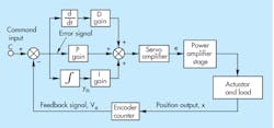
Stability can be achieved in the integrally controlled positional servo only by including other components—namely, proportional and derivative terms. This is where the acronym PID comes from: Proportional-Integral-Derivative control. The classic configuration of PID control is shown in Fig. 5. Note that the derivative and proportional components appear in parallel in the block diagram.
5. Classical implementation of the proportional-integral-derivative (PID) controller is represented in this block diagram.
The presence of the PID components does not diminish the goal of integral control, which is to reduce steady-state error to zero. This can be understood by assuming that the system is stable and is in steady-state, which is not an automatic result of simply putting the components together. Therefore, the output actuator is stopped, the control valve is at null, and the current into the valve is constant and near zero. This requires that the output of the PID summer be constant. If the summer output is constant, the input to the PID integrator must be absolutely zero, even with P and D implemented. But as we have already learned, the input to the integrator is the system error. Therefore, system error must be zero, which is the desired result.
Goals for PID Tuning
Ever since PID was first invented in about 1930, attempts have been made to tune the controller. More recently, controllers have been developed that tune themselves automatically. The automatic tuning algorithms make some assumptions about the machine under control. As a result, no truly universal tuning procedure exists. My aim is not to provide one but, rather, to propose some goals. These goals are needed because if you have tuned the PID to give the optimum response, you need to know what that condition is.
The one criterion of a PID control loop that provides optimum performance is that the servo loop should be tuned for minimum closed-loop settling time. In motion control applications, any constant speed plateaus in the command profile (including any dwell plateaus at zero speed) must last longer than the servo-loop settling time. Otherwise, the servo loop will not reach steady state, and the error will not have been brought to zero.
Assume a “difficult system”—that is, one in which the hydromechanical resonant frequency is much lower than the valve bandwidth. These are the most challenging systems to deal with. In such systems, the servo loop settling time is given by:
Tmin, p = 7.5/(zT ´ z wn),
where Tmin, p is the minimum time to reach steady-state with simple proportional control,
zT is the total damping caused by both mechanical friction and internal leakage across the valve lands or past the actuator, and
wn is the hydromechanical resonant frequency in radians/sec. (not Hz).
When integral control is implemented, settling time increases:
Tmin, i = 10/ (zT ´ z wn),
where Tmin, i is the minimum possible settling time.
The two best ways to use these equations are to first implement proportional control and test the system with step inputs. Secondly, tune the gain until the minimum settling time has been reached. Note that time, then implement integral control. But now you know that the absolute minimum settling time is going to be about one-third greater that the proportional-only settling time. Continue tuning until you get the two times as close as you can. You also will have established the minimum speed plateau times if the integral control is to be effective.
One last item regarding integral control: When the PID controller is tuned for its best response by whatever criterion the tuner uses, it seems as if there is always little or no derivative term. Why is this? I would be interested in hearing from anyone with experience in exploring this phenomenon. Please feel free to email me at [email protected].
