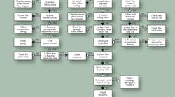
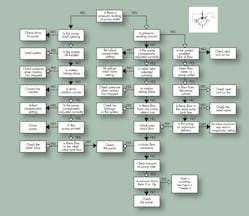
Although the troubleshooting chart in this installment is focused on pressure-compensated, variable-displacement piston pumps, it can be used to check any type of variable-displacement pump.
Compensator setting — Adding pressure-compensation capability to a pump creates a new and important factor to be considered when troubleshooting a circuit. The pressure compensator monitors downstream pressure and automatically changes the pump’s internal configuration to alter flow so as to maintain a preset pressure.
A common problem in circuits with pressure-compensated, variable-displacement pumps is incorrect setting of the compensator cut-off pressure in relation to the spring setting of the system relief valve. The relief valve must always be set higher – 100 to 150 psi — than the compensator. The reason: if the compensator is set higher, part or all of pump output will flow over the relief valve when system pressure reaches the relief valve setting. The compensator will, in effect, be bypassed, and the operating concept for which the system designer specified pressure compensation will be negated. In addition, fluid temperature will rise due to the energy loss resulting from the pressure drop over the relief valve.
Case drain — Another important consideration in these circuits is case drain pressure, which is usually in the range of 5 psi. In many pump designs, the pressure compensator drain flows into the case, allowing pump case pressure to affect the compensator. Should excessive case pressure develop from a partially obstructed case drain line, for example, this additional back-pressure could cause serious problems. An erratic, fluttering compensator could quickly destroy the pump mechanically.
Incorrect pressure — Again, a pressure gauge installed downstream from the pump is a most valuable troubleshooting tool. If the gauge shows no pressure, follow the checkpoints in the extreme left-hand column of Figure 11.
First, note if the pump shaft is rotating and in the correct direction. Next, establish whether lack of system pressure might be caused by an “open system” condition: no resistance to fluid flow because of an open directional control valve or an incorrectly set relief valve. If the pump is not primed, an air-bleed valve installed downstream will help the pump self-prime.
If the system is developing some pressure – but less than desired or required – follow the check points on the extreme right-hand side of Figure 11. There usually is a lack of flow and system pressure because:
- inlet connections to the pump are blocked.
- faulty downstream components are impairing fluid flow and system pressure buildup.
Internal problems — If none of these conditions are found, the troubleshooter will have to examine the internal condition of the pump. There is a fast and easy check to determine if the pump rotating group is worn or damaged resulting in substantial, internal leakage. Using your sense of touch, establish whether the pump case drain line is hotter than the pump outlet line. If it is, shut down the pump, remove the solid piped pump case drain line, and replace it with a hose. Hold this hose over a bucket and restart the pump. Case drain flow will vary with pump size, but if more than a small trickle of oil runs through the hose, you have a very strong indication that the pump rotating group is badly worn.


