Hydraulicspneumatics 2107 Ripley

The Old Timer Part 16: Seeing is Believing

March 25, 2013
The Old Timer of Royal Oak, Mich., was a regular contributor to H&P years before we ever even heard of the internet. But most of his advice is just as ueful — and interesting — today. So rather than leave his wisdom printed on pages archived in our storage room, I pulled out issues from the late 1980s and early 1990s and have been reproducing relevant entries in this blog. Here is my 16th entry, which was originally published in the April 1989 issue: Seeing is believing

The Old Timer of Royal Oak, Mich., was a regular contributor to H&P years before we ever even heard of the internet. But most of his advice is just as ueful — and interesting — today.

So rather than leave his wisdom printed on pages archived in our storage room, I pulled out issues from the late 1980s and early 1990s and have been reproducing relevant entries in this blog. Here is my 16th entry, which was originally published in the April 1989 issue:

Seeing is believing

It seems the labels and nameplates on pneumatic components and equipment always say something about “100 psi.” Most shop people know how difficult it is to get 100 psi air — especially when the compressor is two buildings away and getting old, four new loops have been tapped into the main since it was installed, and every air tool on the premises is running simultaneously. They also know that most of the pneumatic equipment will run just fine at 90 or even 80psi.

However, we had some production people who had seen and remembered that 100-psi note and used it as a ready-made excuse for every production slowdown — air pressure is too low. They caught the ear of the management team with this and the order came down, “Get the air pressure on that line up to 100 psi quickly and make sure it stays there!”

We knew there were a lot of things we could do to improve that air system, be we also felt there was no real urgency to any of them. My boss decided to buy some time for this project.

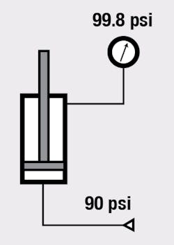
His method: replace all the air gauges on that production line with new liquid-filled pressure gauges. Install a short 1-in bore cylinder with 5/16-in rod between the line and the gauge. Connect system pressure to the cap-end port; connect the gauge to the rod-end port after filling that end of the cylinder with oil.

We now had a little pressure booster in each path to the gauges. Ignoring friction, 90 psi in the system generated 99.8 psi in the annulus end of the cylinder, and that’s what the gauge registered. The production people now could see that they had the 100 psi they thought they needed, and they had to look for other cures for production problems while we worked on the air system at a more leisurely pace.

About the Author

Alan Hitchcox Blog | Editor in Chief

Alan joined Hydraulics & Pneumatics in 1987 with experience as a technical magazine editor and in industrial sales. He graduated with a BS in engineering technology from Franklin University and has also worked as a mechanic and service coordinator. He has taken technical courses in fluid power and electronic and digital control at the Milwaukee School of Engineering and the University of Wisconsin and has served on numerous industry committees.

Continue Reading

Motor leakage variations

Oct. 18, 2006
affect low-speed performance

The Impacts of Electrification on Fluid Power Systems

May 15, 2023
Electrification presents challenges as well as opportunities to re-evaluate and improve upon the design of hydraulics and pneumatics.

Sponsored Recommendations

7 Key Considerations for Selecting a Medical Pump

Feb. 6, 2024
Newcomers to medical device design may think pressure and flow rate are sufficient parameters whenselecting a pump. While this may be true in some industrial applications, medical...

How Variable Volume Pumps Work

Feb. 6, 2024
Variable volume pumps, also known as precision dispense pumps, are a positive displacement pump that operates by retracting a piston to aspirate a fluid and then extending the...

What is a Check Valve and How Does it Work?

Feb. 6, 2024
Acheck valve, a non-return or one-way valve, is a mechanical device that allows a gas or liquid to flow freely in one direction while preventing reverse flow in the opposite ...

The Difference Between Calibrated Orifices and Holes

Feb. 6, 2024
Engineers tasked with managing fluid flow talk about both holes and calibrated orifices, but they are two distinct entities. A hole can be any opening, but a calibrated orifice...