Compressed air is an expensive resource. For each dollar’s worth of electricity used to produce compressed air, as little as 10 to 15% of that energy may be used on the factory in the form of compressed air. As energy costs increase, plant operators need to become sensitive to how much energy and money can be wasted if compressor operation is not tightly controlled, and even the smallest air leaks are not repaired.
When energy was less expensive, manufacturing plants would leave compressors on all the time during a production shift. Then, more than 20 years ago, rudimentary sequencing control systems were introduced that turned compressors on or off in a predetermined order as the plant’s need for air fluctuated. Using sequencers was better than leaving compressors on all the time, but precision in matching air flow with demand was still lacking and energy was being wasted. What was needed was a more predictive and flexible means of pre-emptive compressor control.
Pressure and flow monitoring
Just looking at a system’s pressure and air flow as criteria for making compressor operating decisions is not enough. By the time a pneumatic system’s pressure hits its low pressure set point, or if an increase in flow is detected (meaning the rate of air production needs to increase), the pressure may fall too low before additional compressors are brought on line to begin producing air.
To avoid a low-pressure situation, you could raise the threshold pressure at which additional compressors are turned on, and many plants do just that. But the effect of this is to run the compressor system at an average pressure that is higher than necessary. This wastes energy, and a pattern of doing this may result in the factory purchasing and maintaining more compressors than necessary. Further, systems that run at a higher pressure can leak more and wear out sooner than those that run at lower pressures. All these factors add extra cost to the manufacturing process.
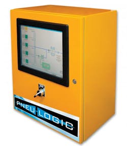
A better alternative is to use a compressor control system that determines which compressors to run using a whole range of criteria, with system pressure and rate of flow being only two considerations. An example of controllers that do this is the PL4000 Series manufactured by Pneu-Logic Corp. The PL4000 balances the supply of air with demand using a proprietary process whereby the controller decides which compressors to run to ensure adequate air supply while minimizing energy use and maintenance costs.
The PL4000’s control algorithm selects which compressor to run based on the availability of compressors and a score that is assigned to each compressor (which serves as a measure of that compressor’s “readiness”). The evaluation process is complex due to the sizeable number of possible combinations in the typical multi-compressor plant. The controller maintains a database of compressor combinations that provides the best performance for different conditions.
Pneumatic controllers
You might think a typical PLC could handle the compressor control task. However, with a large number of compressors, this becomes unwieldy for a PLC program. Furthermore, sequencers generally can’t manage the flexibility required because they are typically hard wired to follow a particular sequence.
The PL4000 selects compressors to run in a two-step process. First, it identifies which groupings of compressors to call upon to provide air to meet a particular need. Second, it selects which compressors to run within a particular group according to their scores.
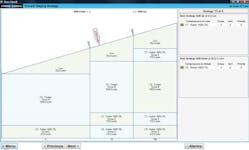
The controller’s display can show, for example, a typical staging table that identifies compressor groupings and associated system pressures they can maintain. Drill-down screens can focus on current flow requirements and show which compressor or compressors would be activated if the flow requirement increases, or if some other factor calls for shutting an operating compressor down.
The control system picks the next compressor to run based on an algorithm that takes various factors into account, including how many hours each compressor has run and when maintenance is scheduled for a particular compressor. The decision is often not obvious: It’s not always economical to simply run the most-efficient compressor all the time. Otherwise, the system would tend to wear out the most-efficient compressor first.
Keeping score
To avoid this, the controller assigns each compressor a run-time score that changes over time as the compressor operates. When a compressor hits a threshold, the control system gives it a break and turns on another from the same group, with a similar capability. Run-time scoring lets the controller predict when operating compressors should be turned off and replaced with compressors in reserve.
Compressors may also be taken off line for maintenance, and the scoring algorithm needs to accommodate that. For example, say a particular compressor’s oil must be changed every 8000 hr of operation. The controller keeps track of operating run time and, as the compressor approaches 8000 hr, the run-time factor starts to affect that compressor’s overall score. This score determines when the compressor will run, ultimately keeping it out of the mix until preventive maintenance is performed.
Compressor controls, such as those in the PL4000, can also enforce operating rules. For instance, efficient operation of a compressor network dictates that only one unit, the trim compressor, will be allowed to run at partial output. The rest should be run at full-flow output.
There may be other external control factors that should be worked into the mix. The control system should accept user-defined inputs. For example, by incorporating production forecasts or production rates, the control system can accommodate compressor maintenance during slack periods, or it can flag when the system will be called upon to operate near its performance limits. The ability to incorporate user-defined functions into the mix can also be used by plant engineers to test different control strategies.
Building intelligence into the compressor controls adds the ability to inform users of system status. Operators would like to know at a glance how the system is performing. For this, the PL4000’s operator screen displays the status of all of the compressors in the network and also allows viewing the operational status of any individual compressor. Because the displays also provide information on the operating efficiency of the system, being able to review real-time results makes it easier for plants to sustain cost-saving initiatives. The PL4000 can also export operational data to a plant’s distributed control system for remote viewing and analysis.
Different plants can have vastly different requirements for compressed air, so a single strategy for compressor control won’t fit them all. In general, though, control strategies that consider usage factors in addition to predicted demand will save the most energy and hold down maintenance costs.
Michael “Dusty” Smith is COO of Pneu-Logic Corp. For more information, email [email protected] or visit www.pneulogic.com.
Benefits of pre-emptive controlAll types of compressed-air applications benefit from pre-emptive controls. For example, paper mills run continuous sheets of raw paper stock at high speed through their machinery. Compressed air is used extensively for instrument air, tensioner control, guides, and air cylinders along the entire length of a paper-making line. If the paper breaks, operators use additional air wands and lances to deal with the initial break and also to re-thread the sheet through the paper machine. This process requires a significant amount of additional compressed air. To meet this surge in demand — while not over-supplying pressure for normal operation — the compressor controller should interface with the paper machine’s controller to allow feedback in the event of a paper break. When that happens, the compressed-air controller should quickly switch to a compressor configuration that will support the coming surge in air demand. In another case, the bagging machine in a baking-soda plant may require a surge in air flow when the machine first comes on line. To support increased air requirements, the controller should activate a special compressor configuration that is established for that purpose, saving time in readying the machine for operation. After equipment is running and pressure has stabilized, the controller switches to a configuration designed for continuous production. An automotive sheet metal plant has multiple work cells for producing different types of parts. The cells typically make parts in batches and are shut down between production runs. Plants can save energy if air flow to idle work cells can be shut off when they’re not in use. If this is handled by the controller, the human-error element of forgetting to turn off the supply at the end of a shift can be eliminated. Various sections of a bottling plant may require different levels of air pressure: high pressure to blow-mold the bottles and lower pressure to operate bottle-filling equipment. The economical way to produce compressed air in this type of application is to organize the factory’s air-supply system into zones with a separate compressor bank for each zone and pressure. The controller should be able to control multiple flow-pressure zones. In addition, high-pressure air may be recuperated from blow-molding machines and used in low-pressure systems as an additional measure to reduce waste.
|
