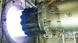
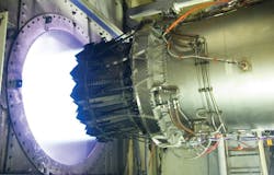
The U. S. Air Force’s Arnold Engineering Development Complex is the most advanced and largest complex of flight test facilities in the world. It can simulate altitudes from sea level to 300 miles, wind speeds from subsonic velocities to Mach 20, and temperature extremes from –85° to 1440° F. The center’s mission is to “test and evaluate aircraft, missile and space systems and subsystems at the flight conditions they will experience during a mission.” Naturally, the AEDC undergoes continuous upgrades in order to apply the latest technology. Recently, Hydradyne Fluid Power completed an automated hydraulic system design-build-install project in excess of $1.5 million for the AEDC.
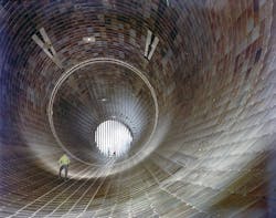
For example, AEDC’s propulsion wind tunnel uses four electric motors driving five air compressors to generate the wind velocities required to simulate actual flight conditions. Two motors are rated at 83,000 hp each, and two are 60,000 hp — a total of 286,000 hp. The electric power requirement is such that the Tennessee Valley Authority, the regional power plant, must be alerted when a test is scheduled. Also, daytime testing cannot occur during the summer months due to the additional power required for air conditioning in that area of the state. This may be the most powerful pneumatic system in the world.
Massive hydraulic servovalves are used to configure the wind tunnel systems for specific test requirements. These valves also provide dynamic throttling to simulate varying flight conditions during a pre-defined test sequence. A need to increase the capability of AEDC’s aircraft engine test wind tunnel necessitated a new hydraulic system.
A look at the new system
The new system is be designed for outdoor installation and rated for a life of 25 years. The majority of system components, including all piping, is constructed of stainless steel, and the hydraulic system’s reservoirs must protect the fluid from contamination.
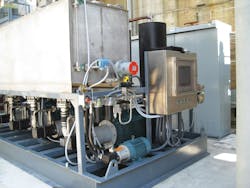
The hydraulic power unit (HPU) consists of four 120-gpm fixed-displacement pumps connected to a common outlet header, each driven by a 150-hp electric motor. Pump suction lines draw fluid from a 1000-gal stainless steel overhead reservoir through a full-port ball valve. The power unit also contains a 20-gpm off-line filtration (kidney loop) circuit. All ball valves have lockable handles and limit switches to indicate fully open and fully closed positions. A 1,000-gal containment drip pan is provided to meet environmental requirements.
The HPU supply and return headers are plumbed to multiple valve actuators, as well as to two accumulator skids that contain a total of 23 Parker Hannifin 10-gal bladder accumulators. The stored accumulator energy combines with pump flow to accommodate momentary peak flow demands. Valves are provided for full-flow flushing of the accumulator skid piping through the return filters during system startup and preventive maintenance periods. This flushing procedure prevents contamination from building up over the years in dead-ended pipe assemblies.
Maintaining fluid integrity
Return fluid from the servovalve actuators is routed through a heat exchanger skid consisting of two air-to-oil heat exchangers, each with a 7½-hp fan motor. Oil then flows through tank top-mounted return filters in the reservoir. The heat exchanger skid contains isolation valves for heat exchanger maintenance, a relief and bypass valve, and two temperature transmitters to monitor oil temperature at the inlet and outlet of the parallel heat exchanger headers. The heat exchangers are sized to maintain fluid at a maximum temperature of 120° F during all operating conditions of the system. In addition, an immersion heater and thermostat installed in the reservoir keep fluid temperature at 70° F during winter months.
The fluid cleanliness for the system was specified to meet ISO Standard 4406 Classification 15/13/11. This is accomplished using a Parker Hannifin 50P high-pressure filter with an 02Q element at the outlet of each pump (plumbed prior to the unloading valve) and two Parker BGT return filters with 02Q elements. Plumbing the high-pressure filter upstream of the unloading valve ensures that pump flow is always filtered — regardless of whether the accumulators are being charged or when the unloading valve diverts pump flow back to the reservoir. After system flushing, fluid analysis tests revealed an ISO 3/3/2 cleanliness level.
The reservoir is a closed system containing four Parker Kleenvent 80-gal reservoir isolators to prevent ambient air from being drawn into the reservoir. The isolators use an elastomer bladder as a lung to provide positive sealing from the outside atmosphere. When the hydraulic fluid level drops, make-up air is drawn from the atmosphere into the isolator. However, the ambient air is contained within the elastomer bladder of the isolator, so it cannot mix with air above the fluid inside the reservoir. This keeps airborne contaminants and moisture out of the hydraulic fluid. Used in conjunction with a water removal filter on the circulation loop, water from rain, snow or internal condensation is excluded.
Flexible control
Automatic system control and monitoring is accomplished using a PLC and industrial panel-mounted computer with touchscreen. The computer and PLC are connected through an Ethernet network that interfaces with the wind tunnel control room, allowing remote control and system monitoring. An operator can monitor oil level, reservoir oil temperature, heat exchanger inlet and outlet temperatures, supply pressure, pump accumulated hours, and current on each phase of the 150-hp motors from a single screen.
The pumps cannot be started unless their respective suction and outlet valves are fully open, and keyed lockout switches disable motor starting when a pump is undergoing maintenance. All filters have electric indicators that monitor differential pressure (∆P) across each filter and display filter status on the screen. Because ∆P indicators only depict a dirty element when oil is flowing, the screens lock in a flashing red indicator. Once the filter element has been changed, an operator must acknowledge the change by pressing the alarm reset button on the screen.
Stainless steel piping per ASTM A312 TP 304 is used throughout the system using butt weld connections. Older systems at AEDC utilized socket weld fittings; however, it was found that contamination had a tendency to settle into the gaps between the pipe and fittings over many years. Nondestructive testing included radiographic inspection of welds and a 2200 psi nitrogen pressure test of all high-pressure pipe runs.
Robert A. Nasca is General Manager of the Hydradyne Fluid Power Tampa Tampa, Fla. branch and author of the book, Testing Fluid Power Components. It is available on Amazon.com by clicking here.
