Editor's note: This is the fourth installment in a seven-part series on digital resolution and other subjects. Read the rest now: Part 1, Part 2, Part 3, Part 5, Part 6, and Part 7.
A variety of issues is associated with the selection of the right speed sensor. The foremost one deals with the type of sensor. Probably not more than three different types are viable with today’s technology:
• rotating ferromagnetic protrusion with magnetic pickup,
• dc brush-type tachometer and
• brushless dc tachometer.
The ferromagnetic protrusions can be gear teeth, a shaft key, a key way (an inverse protrusion), or any other ferromagnetic irregularity of the rotating member.
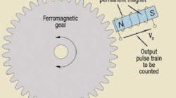
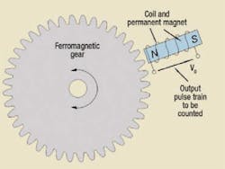
The rotating ferromagnetic protrusion type is widely used because of its simplicity, Figure 1, so this will be our focus. We will address tachometers in a later issue. In the laboratory, it is common to mount a 60-tooth iron gear onto a shaft, then mount a magnetic pickup near the teeth. The frequency of the generated voltage from the pickup is directly proportional to the speed of the shaft, in rpm. All that is needed is an electronic digital counter, which counts the number of pulses that pass during a precisely controlled gate time. If the gate time is set to 1 sec, and the gear has 60 teeth, the frequency, in Hertz, is exactly equal to the speed in rpm.
The gate time does not need to be exactly one second, and the number of teeth or protrusions does not need to be 60, because any combination simply requires a different scale factor to convert frequency to rpm. If there is an onboard processor, scaling is easily accomplished with software.
Problems, delays are common
The first problem that arises with the pulse generation type of speed sensor is that the digital circuitry must accumulate pulses over some finite amount of time. In the digital control world, the sequence typically goes something like this: The computer, by virtue of its programming, “knows” when it needs speed information. It initiates the pulse accumulation process by setting its pulse counter to zero. If a 1-sec gate is used, the data is 1 sec old by the time it is ready. Some people contend that this problem can be overcome by starting the computer 1 sec earlier, thereby preparing the data for when the computer is ready for it. However, this does not eliminate the delay, because the data is still one second old when it is finally available. This strategy can reduce processing delay, but it will not remove measurement delay.
Higher tooth pitch can reduce delays
Reducing the gate time offers a workable solution, but that requires more teeth per unit of circumference to maintain measurement resolution. Perhaps a more viable plan would be to measure the period of the pulse train — that is, the time between two consecutive cycles. That way, the maximum time delay in the data is the time for one tooth to pass. But this is not without its own challenges. If a key or keyway is used as the ferromagnetic irregularity, then the measured time would be the time of one revolution.
If a great number of teeth is involved, the time is short, and an extremely high frequency clock (perhaps several MHz) and high speed counter are needed to maintain resolution. In fact, period measurement argues in favor of fewer teeth, which now raises some practical possibilities. The ferromagnetic protrusions do not need to be gear teeth; they can be any non-uniform iron body. Such a body could be the barrel in a piston pump, a key on the shaft, the vanes in a vane pump, or the teeth of the gears in a gear pump.
The gears could be internal or external. Another problem arises when determining how to mount the magnetic pickup so that the protrusions (whatever they are) can be sensed magnetically, and in such a way that does not interfere with the performance of the hydraulic pump or motor.
Dialed into FM and AM systems
Although it is not generally viewed as such, this is an FM (frequency modulation) system, because the information (speed data) is contained in the frequency of the output signal. It is also an AM (amplitude modulation) system because the amplitude of the voltage varies with the shaft speed and output frequency. The higher the shaft speed, the higher the output voltage. It would be possible to calibrate the voltage with speed; however, frequency is the more reliable measurand.
Whatever is resolved regarding these issues, the electronic circuitry must be able to either digitize the frequency data of the pulses streaming from the magnetic pickup or convert the frequency data into a proportional analog voltage. Inexpensive frequency-to-voltage converters are available commercially and are easy for a competent electronic circuit designer to select. But these devices are not without problems, because they, too, have a considerable time delay associated with the conversion process. In the end, any speed measuring method that uses frequency as its basis will have time lag — and time lag can lead to instability if the speed data is used to close a feedback loop. Delays will also lead to data errors.
Basic Electronics for Hydraulic Motion Control
This is where your basic electronic training starts. This book, unlike many others, is written specifically by a practitioner of the hydraulic art for engineers and technicians working in hydraulics, but it teaches you all you ever needed to know about electronics. Your personal understanding of hydraulics is your ticket to learning electronics with this book, which is filled with analogies to simplify the understanding of concepts.
Everything you wondered about and need is here: transducers, interfaces, signal conditioners, pulse width modulation, controllers, amplifiers, transistors, analog electronics, digital electronics, and much, much more. It is a must read and reference for anyone interested in certification in the exploding technology of electrohydraulics.
It uses your knowledge of fluid power to help you learn and understand electronics. Order your copy now and get the book that makes electronics fun and easy to learn.
Authored by Jack L. Johnson, P.E., edited by Hydraulics & Pneumatics, and published by Penton Media, the hard cover textbook (ISBN 0-932905-07-2)contains 438 pages and sells for $59.00, plus shipping and sales tax. To order, or for more information, visit the Bookstore and download the order form.
|
Solution to February’s blast doors locking up Due to space constraints, we are not able to print this month’s Troubleshooting Challenge, but wanted to provide the solution to last month’s challenge, about a blast door and cylinder that would not move when its directional valve was shifted manually. Hydraulic circuits with pilot-to-open check valves and pressure reducing valves require special consideration and positioning. The installation crew contacted Greg Balzer of Catching Fluid Power and reviewed the circuit with him. The first thing that came to Greg’s mind was his policy of always placing the pressure reducing valve directly under the directional control valve. He and I both feel the general stacking instructions of positioning pressure controls close to the bottom of the stack misleads many designers — and especially assembly mechanics. System relief valves are almost always the first component mounted on the base plate. In most cases, if a sequence valve is used, it is mounted next. However, pressure reducing valves must be positioned to make sure the drain line and pilot signal are properly connected. Some pressure reducing valves manipulate the drain line to determine if A, B, or both ports are reduced. Other brands drain the spring chamber directly to a tank line and use the pilot signal for selecting what ports are reduced. In addition, these valves always bleed off a small amount of outlet oil to the spring chamber to help maintain the reduced pressure control. Pilot-to-open (PO) check valves have a pilot ratio factor that must be considered in most applications with cylinders. The pilot line supply pressure must overcome the pressure trapped between the cylinder and the PO check valve, plus additional pressure caused by the same supply pressure applied to the opposite end of the cylinder. After Greg reviewed the circuit he asked two questions. What was the pilot ratio of the PO checks, and was the pressure reducing valve mounted directly under the directional valve? The installation crew determined the PO check module and pressure reducing valve were switched and not positioned as shown on the circuit. Problem solved! |


