By Eric Cummings and Steve Boyette
Ross Controls
Troy, Mich.
It is easy to say that “Safety is everyone’s goal,” but what is really meant by that? Sound workplace safety practices can reduce the risk of injury to not only machine operators but to other people such as maintenance technicians. Sound workplace safety practices can also reduce the risk of accidental damage to machinery and other company assets, or harm to the environment. Common industry standards acknowledge that there is no such thing as zero risk, but nonetheless provide guidance to machine builders and operators regarding how to minimize risks. This is commonly referred to as machine safeguarding. Here’s a look at some key factors.
Control integrity
The most important point in machine safeguarding i s evaluating the entire system, not just the electrical portion to minimize exposure to unnecessary risk. That’s because systems are rated based on the weakest link in the control chain.
Several standards (including ISO 13849-1:2006, ANSI/ASSE Z244.1 – 2003 (R2008), and ANSI/PMMI B155.1-2006) define the control system as including not only input, sensing, and inter- SAFETY VALVES lock devices but also output devices such as pneumatic and hydraulic valves.
The function of a fluid control valve mimics that of an electrical-control relay and, therefore, is subject to the same rules for classifying safety integrity. Thus, properly specified machine safeguarding systems include provisions for pneumatic valves, including:
• Must be functionally redundant.
• Must be monitored for faults (including diminished performance faults which may create the loss of redundancy) without depending on external machine controls or safety circuitry.
• Must return to a safe position in the event of a loss of pressure or other such event.
• Able to inhibit further operation upon detection of a fault until it is corrected.
• Should have a dedicated, specific functionreset input and should prohibit a reset by simply removing or re-applying pneumatic or hydraulic power.
• Must not automatically reset.
Control reliability is generally considered safety Category-3 or -4 as defined in ISO 13849- 1/ EN954-1 Standard for all types of circuits. This ISO standard regarding Category-3 states”a single fault in any of these parts does not lead to the loss of the safety function” and that “a fault shall be detected at or before the next demand upon the safety function.” And for Category-4, “an accumulation of undetected faults shall not lead to the loss of the safety function.”
Providing control reliability with fluid power is not quite the same as with electrical controls, however. For instance, plain redundancy in a safety circuit requires the equivalent function of four valve elements, not just two. Two of the four valve elements handle the inlet function while the other two elements handle the stop function (energy release). Many self-designed systems risk having hidden, potential flaws, which can lead to unsafe conditions because they are unseen, unexpected and, therefore, excluded from design and safety reviews. A good example is the spool cross-over conditions or ghost positions of a valve, which are usually not shown on schematics.
Two general abnormal conditions can affect valve safety. The first is similar to an electrical-control fault, such as when a relay might be stuck in the open or closed position. The second abnormal condition is when a valve develops diminished performance, as when a valve becomes sticky or sluggish. In these cases the valve reaches the proper position, but slower shifting affects safe stopping distances or precise timing. The ANSI B11.19- 2003 Standard mandates a monitoring system that detects these conditions for critical applications and the ANSI/ PMMI B155.1 standard requires diminished performance monitoring if stopping time can be affected. An easy solution is to use a self-monitoring, Category-3 or -4 valve, designed to detect both conditions.
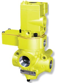
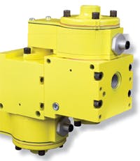
The use of double valves remained relatively unheard of for many years except in a few select industries, such as stamping presses, which first initiated control reliability requirements. Double valves provide dual internal functions (redundancy) so that an abnormal function of one side of the valve does not interfere with the overall normal operat ion. At the same time, the double valves sense abnormal operation on either side of the valve and then inhibit further operation until the problem has been corrected and the valve deliberately reset. This sensing and inhibiting function is commonly referred to as monitoring.
Two standard air valves, whether in parallel or in series, cannot perform the same safeguarding function. By simply incorporating two standard air valves into the circuit, no provision is made to sense abnormal operation of one side of the valve or, even more preferable, diminished performance such as slow shifting. In addition, there is no provision for inhibiting further operation of the circuit until the valve is repaired. If one valve actuates abnormally, the second one continues to function and redundancy is lost. The circuit doesn’t recognize lost redundancy nor would it halt operations as a warning that redundancy has been compromised. Then, if the second valve also actuates abnormally, there is no “back up” and control integrity no longer exists.
Double valves are appropriate for pneumatic and hydraulic equipment anytime reliability is an issue. Typical applications include E-stop, twohand- control, light curtains, safety gates, pneumatic locking devices for safety gates, hydraulic brakes, air brakes, amusement rides, hoists, elevators, pinch-point applications, or any other application where control system integrity depends on valve operation.
Energy isolation
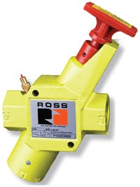
Lockout/tagout (LOTO) is another high-priority safety topic. Under standard LOTO, before a worker can enter a protected area of a machine, all energy must be dissipated and machine-status verified. The standards define “de-energized” as disconnecting all energy sources from the machine and ensuring no circuits contain residual stored energy. For fluid power, this requires a manually operated energy-isolation valve that must:
• Have a secure and tamper-resistant method of lock attachment.
• Be located outside the protected area in an easily accessible location.
• Have a method for employees to verify energy dissipation prior to entering the protected area.
• Not be used in normal production.
• Have a full-size exhaust port (ANSI/PMMI B155.1-2006, CSA Z142-02).
• Be positive acting (only two possible positions).
• Be easily identifiable.
• Can only be locked in the off position.
And, of course, companies must have a written policy and train affected employees.
Alternative lockout
The ANSI/ASSE Z244.1 – 2003 (R2008) standard also addresses other lockout techniques, called alternative methods of controls. These systems can save costs and improve machine up time. But alternative methods only apply to routine, repetitive tasks that are integral to the production process and are based on risk assessment providing effective personal protection. The machine must still have a standard lockout system for repairs and other tasks.
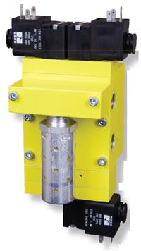
Alternative methods of controls offer two time-saving advantages. First, it uses a single lock-point (a remote, low-voltage system) that simplifies and speeds lockout, and enhances safety by avoiding the chance of a point being missed. The operator need not travel all around the machine to access various points to lockout or unlock operations. These systems place electrical lockout switches, connected to the control system, at locations that require machine access, and incorporate appropriate safety valves for pneumatic and hydraulic lockout.
The second feature of alternative lockout systems is that not all energy needs to be removed. In fact, sometimes removing all the energy creates a more-hazardous condition. This can result in significant time and cost savings when systems contain large volumes of compressed air.
The standard is also useful for tasks that are not routine, repetitive, or integral to production, but require power for, say, troubleshooting a control circuit. The new standard recognizes that there is no such thing as zero risk, and that some risk is present in order to perform certain tasks. In this case, the standard requires that the control system and valve controlling the nonisolated energy be control-reliable, Category-3 or -4.
Risk reduction
There is no such thing as zero risk. Therefore, the standards require an assessment of all possible risks to determine the possible ways for mosteffectively reducing those risks.
The best approach to risk assessment is as a team. One big change ANSI B11.TR3-2000 brought about is that both the machine manufacturer and user are responsible for performing the assessment for new and rebuilt in fluid power.
1. Hydraulic accumulator dump valves, which must be monitored or manually operated.
2. Pilot-operated check valves (PO checks), which are designed to hold a load in place and inherently trap pressure (which must be released during lockout procedures).
3. Use of 3-position all-portsblocked valves, which trap pressure.
4. Hazard created when a hose or tube fitting blows off.
5. Sudden surge of compressed air being reapplied after LOTO, causing cylinders to move quickly and subjecting the machine to shock.
For all of these, and more, a complete analysis of the circuit should be taken to uncover potential hazards, even though the hazards have never occurred in the past. The standards say if it can happen, it must be considered.
| Additional resources |
To design a control reliable circuit, the engineer must be able to break the reliability chain into links. Each link must represent a control device that meets the control reliability specifications listed above. If the device does not meet all these criteria, it is not considered a control device but only a component for integration into a circuit, thus requiring additional components or requiring even a redesign to achieve control reliability.
Updating a system may not be difficult if the electrical controls are already control reliable. Because some valves have all of the monitoring logic built right in, there is no need to modify existing external control circuitry for valve monitoring. Simply replacing existing pneumatic or hydraulic valves with critical-application valves and properly wiring them into the system may bring the fluid controls into a control-reliable performance state.
So, the next time you design a circuit, remember that the ANSI, OSHA, ISO, and consensus standards apply to the entire control circuit from beginning to end and you will not break the chain.
