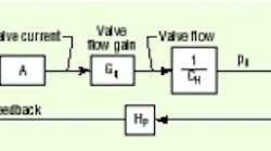
Figure 1. With no through-flow, there is one pure integrator in the loop, making it a Type 1 control system
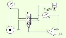
Figure 2. This simplified schematic shows the through-flow path as the dashed line through the load. An analytical schematic would be the same, even if the through path was connected at the valve work port. The important issue is whether flow occurs through the control valve in steady state.
An example of a pressure control system that has through-flow is the SAE test method for hydraulic hose. This test requires pressure to vary between maximum and minimum limits according to a prescribed pressure profile and within a specified temperature range. The easiest way to maintain temperature in test specimens is by providing a flow path (an orifice) downstream of the test hose. This allows fluid to change continuously.
In this and similar cases, the control valve not only must supply the volume of fluid needed to fill and compress the volume, it must also supply any amount of steady-state through-flow that results at the controlled pressure level. A complication is that the through-flow probably varies as the controlled pressure level varies. Therefore, the valve must be open, even when the controlled pressure is held constant at the target value. In addition, some error must exist between the command and feedback. The error is what holds the valve open to supply the through-flow.
Here is the explanation: If the valve is open, the current must be non-zero. If the current is nonzero, the input to the amplifier must be non-zero as well, leading to the conclusion that the error is not zero. If the error is not zero, then it immediately follows that the command and feedback values must differ. The conclusion? A steady-state error in the system is just sufficient to hold the valve open enough to provide the through-flow at the output pressure level, but the command and feedback signals are not the same. This reality places a pressure-dependent flow into the circuit, which creates feedback around the integrating volume that, in turn, eliminates its pure integration function. The integrator is still there. However, the feedback around it converts the mathematical process from one of integration to a nonlinear first order time constant.
Type 0 and Type 1 regulators
To illustrate, the circuit in Figure 1 has no through-flow. Therefore, the controlled volume acts as a pure integrator, leading to the conclusion that the command and feedback are equal when the output pressure reaches the commanded level.
The circuit in Figure 2, with its steady-state through-flow, necessarily has valve opening and current-and error between command and feedback. This is a classic Type 0 regulator. As such, it functions with steady-state error.
The presence of the steady-state error in the Type 0 system often is objectionable because it is more difficult to analyze than a Type 1, zero error system, which can be analyzed "off the top of your head." It is not so easy to analyze the Type 0 system. In the Type 1 system, the command and feedback are, ideally, equal to each other, and the calibration thinking is simple. If you enter 5 V of command, for example, then in steadystate, you expect the feedback to be 5 V as well. Further, if you cali-
brate the feedback transducer for, say, 1 V/1000 psi, then it is simple arithmetic to conclude that a command of 5 V will result in an output pressure of 5000 psi.
But with the through-flow of the system under discussion at the moment, an error must exist between the command and feedback in order to sustain the through-flow. In such a situation, the command will always be greater than the feedback signal, and the calibration factor for the pressure transducer will not be the same as the calibration for the feedback control system.
Take the above data for instance, calibrated for 1000 psi/V. If an error of 0.5 V is needed to hold the valve open enough to maintain through-flow, then a command of 5.5 V is needed to get a controlled output pressure of 5000 psi. Note, then, the balance at the input to the amplifier: 5.5 V of command, minus 5.0 V of feedback, equals 0.5 V of error. Recall that this is the amount of error needed to hold the valve open enough to sustain the through-flow. In the Type 1 system, it is only necessary to know the calibration on the feedback transducer. But in this, the Type 0 system, we need to know the gain of the forward branch as well. You may get the idea that if 0.5 V of error is needed to hold the valve open the right amount, then why not just use op-amp circuit function, (called an offset) to add in 0.5 V? Voila, you'd have the required voltage for through-flow purposes, and the command would only need to be 5.0 V. On the surface, this appears to be a simple way to get the calibration of 1V/1000 psi. But there is a flaw in this logic. However, the 0.5 V of offset is correct only when the commanded target pressure is 5000 psi. If the target pressure is different, so is the amount of offset.
The reason this is true can be seen by looking at the hydraulic circuit and answering the question, "How far must the control valve be open under a variety of target pressure levels?" First, note that the through-flow results from some unspecified, but real, orifice offering a continuous flow path through the circuit. Because the opening is an orifice, the flow through it will depend upon the pressure.
Therefore, as the target pressure changes (hopefully, the output pressure changes along with the changing command), the through-flow must change. More specifically, the through-flow will increase with increased commanded pressure. The only conclusion we can draw is that because the through-flow is higher, the control valve will have to open farther at the higher pressures than at the lower pressures. If the valve must open farther, then the current into the valve must be greater, requiring a greater error.
Details on this subject, including formula derivations, are available in Designer's Handbook for Electrohydraulic Servo and Proportional Systems. For more information, contact IDAS Engineering Inc., at (262) 642-7021; fax (262) 642-7025; or www.idaseng.com. The book is also available from Barnes & Noble.
The website describes testing, research, and design facilities and services, instructional videos, books, and software, all geared toward electrohydraulic system design. It also contains complete, unedited versions of this and previous "Motion Control" columns.


