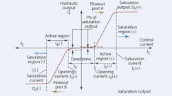
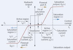
Although it is more detailed than what you'll typically see in technical literature from valve manufacturers, Figure reveals several key valve operating characteristics:
• opening (cracking) current,
• width of the dead zone,
• width of active region,
• saturation flow,
• flow gain, and
• linearity.
The valve cracking point is that instant where the valve just begins to open. That may seem a simple and clear statement, however, it is not. Because there is always leakage in spool valves, flow variations take place all through the overlap, or dead zone of the valve. (The dead zone is the very low-flow region that exists between the two cracking points.)
Therefore, knowledgeable people must agree on how much output flow constitutes valve opening. ISO 10770-1 presented an opportunity to set an international standard value. However, the formulators of that document chose expediency and avoidance of controversy over enlightenment, and said nothing.
The Milwaukee School of Engineering, the beneficiary of an industrial research project some years ago, took a stand to define the condition of valve opening as "that point where the output flow has risen to a value of 1% of the full-shift flow." It is a good definition because it is based on the practical features of spool valves. With it, more parameters can be defined.
Rated flow can be determined from the metering curve of Figure 1, as long as the supply pressure is set to and maintained at the valve's flow rating pressure:
QS = QR ÷ PS,T = PS,QR
Where:
PS,T is supply pressure when making the metering curve, and PS,QRis the supply pressure used for flow rating purposes.
For servovalves (ISO 10770-1), the standard test pressure is 7 MPa (1015 psi). Proportional valves are rated at 1 MPa. The formulators of ISO 10770-1 could have defined servo and proportional valves, but they chose not to. Instead, they avoided controversy and responsibility by instructing the reader to test at 7 MPa or 1 MPa, "as appropriate." Thus, the difference between a proportional valve and a servovalve is based not on performance differences, but rather by the pressure at which the flow rating test was conducted.
Defining a gain plan
Flow gain is the rate at which output flow changes with respect to change in control input current. With no differential load pressure:
For non-linear valves, it may be advisable to determine the average flow gain. Unfortunately, there are several ways to define an average flow gain for a non-linear valve, all of which yield different values.
On the other hand, flow gain is not a very important valve parameter. This is because the valve pressure drop is always changing in the application. Consequently, the flow gain is always changing.
More important is the velocity gain of the actuator relative to the valve's input control current. Because of the square/square-root relationship between flow and pressure drop, flow gain can be evaluated at test pressures other than the flow rating pressure. Furthermore, flow gain can be calculate for pressures other than the flow rating pressure:
Where: GQ, APPis the flow gain in the application, GQris the flow gain derived from rated flow while operated at rated pressure,
PSAPP is the supply pressure at application time, and
PSQR is the test pressure used to flow-rate the valve.
Flow gain often is quoted by users and manufacturers of servovalves and sometimes for proportional valves. However, its importance is overstated. A far more important system parameter is velocity gain, which is application related. It accounts for the flow gain of the valve, the actuator size or displacement, the load on the actuator, and the supply pressure. In contrast, flow gain is a valve-only parameter, and it is valid only at a specific supply pressure. Furthermore, flow gain does not in any way account for the myriad variations in the application, such as actuator size, load, and supply pressure.
Linearity or non-linearity?
Technical literature always reports linearity of a valve's metering characteristics. Actually, it is evaluating the valve's non-linearity. For instance, one popular servovalve is listed as having "linearity of less than 3%." If the valve is only 3% linear, it must therefore be 97% nonlinear. It is difficult to even imagine such an abomination! Clearly, that is not the interpretation intended by the valve's manufacturer in expressing linearity. What is meant is that the valve is 3% non-linear and, therefore, 97% linear.
A much more important valve parameter is the dead zone. A valve with substantial dead zone is rendered useless in applications that seek null as the ultimate operating conditions, such as in positioning systems and some pressure-control systems. Unfortunately, the electronic dead zone compensators that are prevalent in both analog and digital valve controllers, although helpful, can never truly compensate for valve overlap.
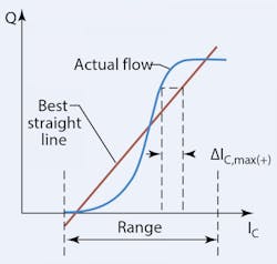
In essence, linearity is the degree to which the metering curve agrees with a best fit straight line, Figure 2. Linearity is only marginally important, and it is easily corrupted by unscrupulous reporters. In order to fit and compare the straight line, the range limits over which the fit is to apply has to be defined. In Figure 2, the limit for the straight line has been chosen as, nominally, the active metering zone of the valve. An evaluation based on the maximum deviation between the metering curve and the straight line (with smaller deviation being better linearity) will produce a higher value than if the straight line were rotated counterclockwise about the point where the two curves intersect. On the other hand, if the straight line passes through the origin, a much higher degree of non-linearity results. Reporting standards, such as ISO 10770-1, are totally silent on how non-linearity should be measured and reported.
Hysteresis
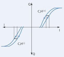
For a proportional valve, hysteresis is the point of widest separation between the metering characteristic curve with increasing input relative to the characteristic with decreasing input, as measured along a horizontal line. This idea is presented in Figure 3 for a proportional valve with substantial overlap. Note that with an overlapped valve, the maximum horizontal separation is evaluated for both Aport output flow and B-port output flow. However, the delta values are divided by the total current difference between negative saturation and positive saturation (Figure 1 defines the values for IA(+) and IA(-) as applied to the following formula):
For a zero lapped servovalve, the approach for evaluating the hysteresis is a bit simpler. There is no distinction made between the positive and negative flow portions of the metering characteristics. The entire metering curve is scanned for both increasing and decreasing input current, the widest horizontal separation is reported, and the hysteresis is evaluated as:
Where IC,His the widest separation between increasing and decreasing input characteristic found anywhere on the metering curve.
Over the threshold
Threshold is an attempt to separate and measure the portion of valve hysteresis caused by friction from the portion caused by the magnetization properties of the torque motor's internal ferromagnetic parts. In that respect, threshold represents the very minimum possible hysteresis when all the magnetic effects have been eliminated. Indeed, it is a property of iron that when a point on the magnetic curve is approached in a cyclic and decreasing manner, the magnetic hysteresis is greatly reduced. Now, when a servo loop is tuned for high gain, the null point can be approached in just that way. Therefore, the ultimate accuracy of the servo loop is better assessed by the threshold, rather than the hysteresis. In addition, whenever integral control (PID control, for example) is implemented with hysteresis in the loop, the servo loop will exhibit a low level, steady, oscillation that gain adjustment will not eliminate. This condition is called a limit cycle and is one of the many reasons why integral control should not be used in some applications.
The test for valve threshold is difficult to conduct, and it is affected by both operator technique and sensitivity of the instruments used for measurement. Threshold is reported as the ratio of the current change required to effect a reversal in flow increase, divided by the rated current of the valve. For servovalves, a typical value is about 0.5%. It should be apparent that threshold tests are not conducted on overlapped valves.
Details on this subject, including formula derivations, is available in Designer's Handbook for Electrohydraulic Servo and Proportional Systems, by Jack L. Johnson, P.E. o order, or for more information — including a detailed table of contents — visit the H&P Bookstore by clicking here.
