Factory operators are posed with the need to make their operations ever more productive in order to keep up with competitive pressures in the marketplace. At the machine level, this often translates to the requirement for higher speed and precision from motion components in the system.
Valve sizing
With linear actuators, given the length of stroke and time of motion required for the application, system designers should start by determining the diameter of the cylinders. The reason for focusing on cylinder size first is to ensure adequate dynamic response, in order to meet acceleration and deceleration requirements. This usually requires calculating the needed system pressure, as well.
The next step is typically to choose the size (flow rating) of the valve — relatively easy once the correct diameter of the cylinder is calculated. Note that servovalves and servo-quality proportional valves are generally rated at 1015 psi pressure drop, whereas other proportional valves are often rated at 145 psi pressure drop. The difference is significant — the flow at 1000 psi pressure drop is typically about 2.65 times the flow at 150 psi. Choosing the correct valve is more than sizing, however, since there are usually many functional options for each range of valve size.
Valve choicesThe basic decision is whether to use servovalves or proportional valves. The main difference between them is how the spool is shifted. Proportional valves use an electric coil and magnet, like the voice coil of a typical audio speaker, to directly move the spool. Servovalves use a small torque motor to control hydraulic pressure, which in turn moves the spool (pilot-actuated).
The response of these two valve types differs because of the force available to shift the spool. Servovalves generally respond faster than proportional valves because of the ratio of hydraulic forces to the mass of the spool, although some proportional valves approach servovalve response times. Proportional valves must supply enough force to move the spool, the inline LVDT, and the solenoid core, as well as overcome spring centering forces.
The precise machining and small orifices associated with pilot-operated servovalves drive up the cost and make them more susceptible to contamination. In many applications, this has steered people away from servovalves and toward proportional valves. However, servovalves still have their place. For example, servovalves often work better on high-flow applications, where system pressure is available to move the spools and oppose the higher flow forces. In these types of applications, servovalves are a safer design choice and perform better because they have a faster and more linear response (and hence are easier to control).
In some cases, proportional valves will not have enough power to overcome the Bernoulli forces caused by high flows. In these cases, the valves will appear to lose control momentarily until the flow forces are reduced. While troubleshooting, there may be a tendency to fault the device controlling the valve instead of the valve itself. An oscilloscope or another diagnostic tool that can record control signals, spool positions, and actuator positions is valuable in these cases.
To solve this flow force problem, one can use a multiple-stage valve. Flow from a small pilot valve is used to control the spool position of the main spool. Multiple-stage valves are more expensive and can be much slower, as there are multiple stages causing phase delay. However, large valves require more force to quickly move the main spool than what an electric solenoid can provide alone. In these cases, the pilot valve enhances performance by directing oil pressure to move the main spool quickly.
Proportional valve amplifiers
Proportional valves need an amplifier to convert the motion controller's control output voltage signal-to a high current signal to move the spool. With a servo-proportional valve, this amplifier uses the spool position feedback from the LVDT in the valve to correct the error between the control signal and the LVDT feedback. To accomplish this, the error between the control signal or reference and the feedback is run through an electronic servo-amplifier. Some of these amplifiers use simple proportional control, whereas others use PI or PID control. If these amplifiers are not "tuned" for the valve, the valve performance will suffer. It is best to purchase proportional valves with their own onboard electronics to help ensure the amplifier is properly tuned. Amplifier cards can be purchased separately, but this requires additional effort and knowledge of how to adjust the gains in the amplifier so the spool will respond quickly to the control signal.
Spool choices
Proportional valves are so named because the valve spool shifts in proportion to the control signal driving the valve. However, flow is not necessarily proportional. Proportional valves may have many different types of spools — and making the correct spool choice is critical for maximizing system performance.
For position and pressure/force control, a proportional servo-quality or axis-cut spool should be selected. These spools provide flow proportional to the control signal, providing that pressure drop across the valve stays constant. These valves have a constant gain because the response is linear, Figure 1(a).
Closed-center spools
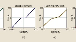
There are many forms of nonlinear spools with many names. The most common is the overlapped or closed-center spool that appears to have a deadband, or zero gain, region because the valve ports do not allow flow while the control signal is small, Figure 1(b). This may reduce leakage and make it easier to keep a system stopped while in manual control, but it also makes these valves poor choices for position or pressure control applications, because the spool must be shifted very quickly across center to provide fine pressure or position control.
The larger the deadband, the longer it takes to shift the spool across it. During these few milliseconds, there is essentially no flow response from the valve — resulting in no change in position and pressure input to the motion controller. This discontinuity in feedback reduces the ability for a motion controller to maintain precise positions or pressures. Closed-center valves should only be used on applications where the spool does not need to shift quickly across the deadband, i.e., where motion doesn't change direction rapidly or often. Speed control applications like conveyors are good examples of these applications.
Dual-or variable-gain spools
Other spools have flow gains that vary with the control signal. These valves usually have low flow gains while the control signal is close to zero and higher flow gains as the signal approaches ±100%. Notch or dual-gain valves have distinct low and high gain regions, Figure 1(c), while curvilinear valves have continuously varying gains, Figure 1(d). For manual systems, this results in fine control at slow speeds while providing a lot of flow for high speeds.
Although not a problem with manual or open-loop control, the non-linear valve makes the whole system non-linear — so closed-loop control is difficult. The closed-loop controller is required to change its gains on-the-fly as the valve shifts between high-and low-gain regions. In theory, this valve linearization (compensation for the varying gains as a function of the control signal) can be done within the motion controller, using a look up table or a specific formula.
The need for matching the characteristics of the specific valve limits the usefulness of this approach. Notch spools can work well in machine applications where closedloop control is only required at slow speeds. Open-loop or manual control can be used at higher speeds, where the valve is in the high gain region. This way, the closed-loop controller does not need to change its gains on-the-fly as the valve shifts between high and low gain regions. However, for most position or pressure control applications, it is better to avoid notch or curvilinear spools.
Valve response and ratings
Another reality to contend with is that the valve performance curves shown in manufacturers' catalogs are not all generated under the same conditions. Different manufacturers may rate their valves at different amplitude of spool travel.
The response of the spool travel is usually much worse for 100% control signals than for 5% control signals. This means that two valves rated at 30 Hz may actually be quite different if one is rated using a 5% control signal and the other valve is rated using a 50% control signal. Many of the performance curves show the response for a 5 or 25% sine wave.
These 5% ratings are good for applications that require dithering the valve around 0%, such as pressure or force control applications. They are not useful for high speed applications, were the valve spool must travel almost 100%. A safe rule of thumb to follow is to take the rise time from 0 to 100% and multiply it by 4, then divide this time into 1 to get the frequency for full travel.
Linear valves with a fast response are necessary for high performance position/pressure control systems. Of course, valve performance is not perfect, and a good motion controller is still required to compensate for the valve response and the mass and spring effect of the actuator and load. To realize the full performance of a well-engineered hydraulic system, select a motion controller designed for use with hydraulics, having features such as separate extend and retract gains, position-pressure/force control, and the ability to connect directly to magnetostrictive linear displacement transducers.
Conclusions
Detailed thought and analysis should be given to the selection and sizing of the hydraulic components before beginning to work with the motion controller. Choosing the correct valve is not always easy. The lack of standardization in valve ratings makes comparing valves difficult. For position or pressure/force applications, use axis-cut valves (linear spool with zero overlap). Some deadband may be permissible for applications that don't require the spool to shift through zero; however, the flow response should be linear throughout the rest of the range.
Peter Nachtwey is president of Delta Computer Systems, Inc., Vancouver, Wash. For more information, visit www.deltamotion.com.


