As those schooled in fluid power control well know, there are three general types of power sources in use today:
• the constant pressure source, better known as a pressure compensated pump with an augmenting accumulator,
• the constant flow source, better known as a fixed displacement pump, and
• the variable displacement pump configured to provide flow control rather than pressure control.
Each source can be used for pressure control, and each provides its own peculiarities, advantages, and disadvantages.
Constant-pressure sources
Previous discussions were based primarily on the presumption that the power source would be constant pressure. In such systems, the electrohydraulic interface device — that is, the device that converts electronic input signals to output hydraulic signals — invariably is a directional-control valve. It can be a two-, three-, or four-way valve, with the type of valve determined by the needs of the application.
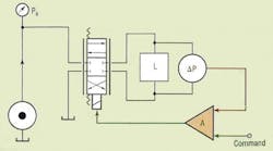
It is probably safe to say that the four-way directional control valve will always work in the valve-controlled pressure control system. It is shown in a simplified schematic in Figure 1. The first advantage of the four-way configuration is that it can control not only gauge pressure, but differential pressure, as well. In fact, if differential pressure needs to be controlled, which might be the strategy used to regulate torque from a hydraulic motor or rotary actuator, then a four-way valve is required.
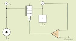
On the other hand, if pressure in a volume must be controlled, then a three-way valve will suffice. In the three-way circuit, the valve's powered land opens to raise the pressure and the valve's return land opens to reduce the pressure. There can be through-flow or no through flow, depending on the application. Assuming it has been properly sized and has adequate frequency response to meet all the performance requirements, the three-way valve will suffice. If there is no through flow, then the energy stored in the compressed volume forces the exhaust flow through the return land and back to tank, thus reducing the output pressure.
Further consider the three-way control valve in the pressure control system, especially when substantial through-flow exists. If a large through-flow exists that has sufficient fluid conductivity to meet worst-case pressure fall rate, then the three-way valve never has to cross over center to reduce the pressure. In fact, a through-flow rate can be so large that the threeway valve has to remain open to the powered land in order to prevent the controlled pressure from dropping too fast.
General requirements
At this point it may be wise to backtrack a bit and discuss the performance requirements of pressure-control systems in general. Output pressure often must follow some command input at some specified rise rate, and it must do so within some error tolerance while sustaining some through flow. Such a case exists with the SAE hydraulic hose test procedure.
Thus, the pressure control system (the directional-control valve) must be sized to supply the pressure-dependent through-flow plus the flow of compressibility. In applications with zero through-flow, the valve must be sized only large enough to supply the compressibility flow. Compressibility flow is the product of the hydraulic capacitance and the rate of pressure rise or fall. The larger the volume under pressure or the higher the pressure rise rate, the higher the flow must be and the wider the valve must open.
Two critical points usually exist in meeting pressure rise and fall rates that represent worst-case design scenarios. The first is in maintaining the specified rise rate just as the highest controlled pressure is reached. The second is in maintaining the specified fall rate just as the lowest pressure is reached. These two points are where the valve must be opened by its greatest amount when there is no through-flow.
Clearly, then, when there is through-flow, the more severe requirement regarding valve size usually occurs just as the highest pressure is reached. This is because the pressure rise rate must be maintained, which requires a sustained flow of compressibility, and the through-flow must be maintained. These two flows must be supported at a moment when a minimum differential pressure exists across the powered land. Again, if the through-flow is sufficiently large, it may not even be necessary for the three-way or four-way valve to cross over the null (center) position.
Two-way and three-way?
Some important points must be made regarding three-and fourway valve control of pressure.
Consider the three-way control valve in the high through-flow situation. If the valve doesn't have to cross over center, then the degree of overlap of the valve is unimportant. This means an overlapped proportional valve will suffice if its frequency response meets the accuracy requirements. This is important, because zero lapped valves should be avoided due to their high cost.
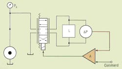
If the valve never crosses over center, even under worst-case conditions, a three-way valve is unnecessary. A two-way valve will suffice, and the feedback control system merely needs to control the degree of opening, as shown in Figure 2. Of course, the circuit has to be carefully analyzed in a quantitative-sense so that these design decisions can be made before committing to hardware.
If differential pressure is controlled, and the algebraic sign of the pressure must be reversed, then the valve must always cross over center, even with through flow. This makes the degree of valve overlap critical. In such situations, a zero lapped valve is normally called for. The circuit configuration is shown in Figure 1.
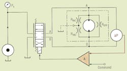
Three possible through-flow paths exist for differential pressure control. The first is from one valve port to tank, the second is from one side of the load to the other, and the third is from the opposite valve port to tank. This is precisely the situation that exists when the load is a conventional, continuous rotation hydraulic motor, Figure 3. The valve must account for internal leakages and compressibility flow and simultaneously maintain a targeted differential pressure.
Fixed displacement, constant-pressure sources
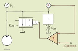
The fixed-displacement pump can be used with valve control in order to control output pressure. A simplified schematic of such a system is shown in Figure 4. The single control orifice coefficient is labeled KVBP. The major advantage of this system is that it uses a simple two-way proportional or servovalve connected to normally bypass at zero control current.
The valve is the single means by which the pressure is controlled. With no current into the two-way valve, it is in total bypass, and the controlled pressure will be minimum. With increased current, the valve moves toward the blocked condition, and the pressure will rise. Maximum pressure is determined by the value of KVFTand the pump output flow. If there is no through-flow (KVFT = 0), then some pressure limiting is needed.
The system functions best when the load is a simple dead volume, with or without through-flow. When the valve is open, the pressure is at minimum, but the pressure cannot be zero unless the pump is shut off. The orifice coefficient of the fully opened valve and the pump's maximum flow will establish the minimum pressure. No matter how large the valve, there will always be some pressure.
Not shown in the illustration is a relief valve, which is needed to limit the maximum pressure. If, for example, the load is a motor or rotary actuator, then the maximum pressure limit most likely is determined by the maximum specified output torque, plus some margin for mechanical inefficiency.
With the control valve fully closed (and if pressure is still below the relief valve cracking pressure), all pump flow goes into the compressing volume and supplying any through-flow. The through-flow requirement at maximum pressure and the hydraulic capacitance of the load can be used to size the pump if there is a specified pressure rise rate. That is, with the valve completely shut off, the total pump output flow, minus the through-flow, establishes the pressure rise rate in the load capacitance.
