It is well-known that a distinct frequency can exist in the hydromechanical system that arises from a load mass interacting with the combined effects of hydraulic fluid compressibility, flexure in the mounting apparatus, and fluid conductor expansion and entrained air. It is symbolized as ƒn and can be reasonably estimated from:
ƒn = ACYL / 2 π (MEQ CH)1/2
where ACYL is the average of the two wetted areas of the stroking cylinder's piston, MEQ is the equivalent mass as seen by the cylinder rod, and CH is the hydraulic capacitance born of compressibility, expansion, and flexure.
The idea that compressibility and other contributing factors can be treated as a hydraulic capacitance was cited as early as 1950. It has also long been known that a lack of rigid machine mounting will result in an even lower resonant frequency. Hydromechanical resonance manifests itself in actuator motion that is oscillatory, or springy.
This resonance, or springiness, is caused by the exchange of energy between the system mass and fluid compressibility. The mass carries kinetic energy as a result of its velocity, and the fluid stores potential energy in its necessary pressurization. So, as the oscillations continue, energy is being exchanged between mass and fluid. If the oscillations subside, then the oscillatory energy must be dissipated. The tendency to oscillate can be seen by recording and reviewing oscillographic traces of actual operating machines.
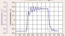
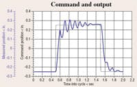
Figure 1. Command and output response of the proportionally controlled system at MSOE clearly show the springiness caused by hydromechanical resonance.
Click image for larger view.
Figure 1 shows the measured response of one of the positioning systems in the Motion Control Laboratory at the Milwaukee School of Engineering (MSOE). The circuit is configured in a closed-loop, positional servomechanism under computerized motion control. The computer generates a square wave position command, and the cylinder attempts to follow the command. However, because of low hydromechanical resonant frequency, the output motion is oscillatory. The system was deliberately constructed with several feet of hose between a servovalve and cylinder, which increases system capacitance (effective compressibility) and lowers the resonant frequency. Such springy motion is undesirable in most applications.
Oscillation and instability
Control system engineers have been working to deal with springy systems for more than 100 years because they exacerbate the stability problem in closed-loop systems. Instability, to a controls engineer, is a condition wherein the system oscillates continuously, without abatement.
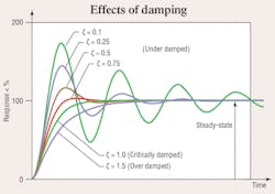
Clearly, this condition is unacceptable. One of the major contributors to the oscillatory condition, just as important as the resonance itself, is the system damping ratio, normally evaluated with the symbol ζ (lower case zeta). Figure 2 is a universal graph of responses of a springy system that is evaluated with different degrees of damping; that is, different values for the damping ratio.
The damping ratio, at least for the current purposes, is a dimensionless number between zero and one. Damping ratio is a measure of the degree to which the oscillatory condition subsides (decays). The higher the damping ratio, the less oscillatory the system becomes.
Figure 2. Under damped, critically damped, and over damped responses in a system with resonance. The under damped case is the one most likely to occur in hydraulic circuits.
Click image for larger view.
If the damping ratio is one, no oscillation or overshooting occurs in the system. If the damping ratio is zero, the system will oscillate without decay, often resulting in the machine destroying itself.
Such a condition can occur in any feedback control system, and, obviously, must be avoided So, the solution is simple: to avoid oscillation, just increase the damping ratio. This begs the question, “What physical parameters contribute to increased damping ratio?” The mathematics of control systems are very specific, revealing two factors that control hydromechanical damping ratio: mechanical friction and internal hydraulic leakage.
This revelation is profound. To increase the damping ratio, we must increase the mechanical friction and increase internal leakage! It may seem heretical in this period of high energy cost and demands for high efficiency to call for such actions. However, the needs of efficiency are at cross purposes to good control! Hydraulic component design engineers have worked for years to reduce friction and leakage, but the controls engineer seeks to put them back into the system.
This is literally true. It is common practice to add damping to a hydraulic system by providing a leakage path around the piston of a cylinder. Mechanical friction, due to its erratic, stick-slip tendency, is a poor way to introduce damping, but an internal leakage path provides damping without the stick-slip, so it is practical.
It is also true that the design for absolute stability (non-oscillatory conditions) in electrohydraulic systems hinges on the inefficiencies in the system. This may not be obvious, but, nonetheless, is true. This is why feedback control system design can be so challenging. Tuning of the controller — setting of the system gains — requires settings that are totally governed by friction and internal leakage.
Further complicating the design challenge is that these system parameters are the least well-known. For example, all servovalves have cross-port, internal leakages totally dictated by the clearance between the spool and its bore and the physical length of the overlap when the spool is centered.
These factors result from manufacturing tolerances. Therefore, they have random elements to them from valve to valve. Thus, one system may be stable and behave in an acceptable manner, but, when the valve is replaced, because internal leakage is different, behavior may be unacceptable, or gains must be reset.
Seeking a solution
So what am I advocating? Do I demand that our components be less efficient? No, but I am advocating that there be clear recognition of the causes and corrective actions available. Adding leakage is one of them, and will result in reduced efficiency. But if good control is the overriding objective, then that’s the price that must be paid.
On the other hand, control methods are available that simulate real, physical damping, and they can be just as effective as real, physical damping. Pressure or acceleration feedback and position feedback are two possibilities that can provide dramatic improvement in system performance. The price to pay is additional feedback transducer cost and additional complexity in system tuning.
|
How to deal with hydromechanical resonant frequency Effects of Inertia on the Hydraulic Servo Mechanism shows a cyclic machine, typical of many industrial and mobile applications, that is subjected to an ever-increasing inertial load. Machine operation is monitored by position and pressure transducers with outputs displayed on an oscilloscope. Merely by looking at the behavior of the machine, it is obvious that high inertia and low damping have a devastating effect on system performance. The video consists of 24 minutes of lab footage showing the effects in real time. It also contains a one-hour lecture explaining what is happening in the video. The aim was to be instructional, and it successfully achieves that goal. A workbook accompanies the video. Four Methods for Controlling the Difficult Machine takes on the challenge of designing around a system plagued by high inertia and low damping. Such machines are referred to in the video as “difficult machines”, for reasons that are obvious in viewing their operation. This video tackles the difficult machine head-on and shows four different methods available to the systems design engineer when high inertia and low damping must be accepted. The methods are both hydraulic and electronic and include controller software possibilities. Again, the video contains actual lab footage of the machine in operation, including footage showing the effectiveness of the four different corrective methods. A one-hour lecture gives a detailed explanation of the concepts behind each of the four methods, and a workbook accompanies the video. Learn details about these and other educational products by visiting the H&P Bookstore by clicking here. |


