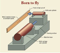
A flying cutoff requires accelerating a knife to the same speed of a moving workpiece, then actuating a knife to cut the moving material at a specific location. Because the work material moves at a constant speed, the process is much more productive than having to repeatedly start and stop the material.
Those of you who regularly read this column are well aware that I am a strong advocate of using servo and proportional valves. Indeed, they represent the best means of critical control. Only valves have the frequency response necessary to provide system responsiveness and overall performance for tight, closed-loop electrohydraulic control.
The other viable hydraulic control method is pump control, where pump displacement is changed in order to change the speed and power output of an actuator. Its main advantage is that it is very efficient because no power is developed by the pump until the load needs it. Load-sensing and pressure compensated pumps perform in this manner and are broadly implemented primarily for their efficient operations.
However, state-of-the-art pump controls lack the system bandwidths needed for critical applications — closed-loop positioning circuits, for example — because pumps do not have the required frequency response. Valves can reach into the 150 to 200 Hz frequency responses, whereas the fastest pump frequency response is a small fraction of that.
Hopefully, pumps will be developed one day with bandwidths of 50 or 80 Hz, or maybe even higher, making them suitable for many applications that are currently controlled by servo and proportional valves. In the short term, however, pump response is in the 20 to 30 Hz range.
Other side of the coin
Valve control does have two major disadvantages: It does its control work by consuming power, not by not generating it, and, it is impossible to have an energy regenerative circuit in which kinetic energy stored in the load can be returned to the electrical power grid during periods of deceleration. Valves provide what is called the energy loss method of control. On the other hand, properly controlled, variable-displacement pumps perform their control tasks by not generating power when it is not needed. This is the energy conservation method.
To get a visualize of the energy loss method, consider an application, say a flying cut-off, wherein a knife-carrying axis accelerates to synchronize with the speed of some continuous moving work material. The knife is thrust through the work piece, cutting it to the precise required length, the knife is retracted, then the knife-carriage axis reverses direction and flies back to home position to wait for the cut of another work piece.
A very tight positioning servo loop must be used to maintain the cut-off accuracy. For high system cycle rates, only valves will be able to perform these tasks. This requires a well-regulated, constant supply pressure to power the servovalve. Such machines sometimes operate 24 hours a day, seven days a week.
Where has all the power gone?
Look at the power consumed in the process, but more specifically, look at how it is consumed. Consider the hydraulic power flowing into the pressure port of the valve. It varies as the actuator speed rises and falls (acceleration and deceleration periods), but it is unidirectional, always flowing into the valve. The power into the valve is the average P-port flow times the constant P-port pressure. If the motion cycle of the knife carriage and cut-off axes is always the same, hour after hour, and if the supply pressure is always constant, the power into the valve is the same, hour after hour. Where does that power go? Well, let's find out.
When the knife axis is accelerating, the valve opens, power flows into the cylinder, and the mass of the axis takes on kinetic energy. Some power is consumed in the open valve land because of its inherent restriction. The remaining power goes into accelerating cylinder and load.
During the constant-speed portion of the cycle — that is, the period of synchronizing the knife axis speed with the moving work material — some power goes into overcoming the friction in the seals and bearings. However, nothing is required to sustain the constant speed of the knife carriage. After the knife axis performs the cut-off, the valve for the knife carriage axis closes off in a controlled manner, causing the carriage axis to decelerate, reverse direction, accelerate in retraction, fly back toward home at constant speed, then decelerate into the home position.
How much of the energy that went into the P-ports of the valves — both the knife carriage axis and the cut-off axis — made its way into the work piece during one complete cut off cycle? The correct answer: Only that small amount of energy that was used to force the knife through the workpiece. Where did the rest of the energy go? The correct answer: Except for a tiny portion that went into the bearing and seal friction, all of it went into the valve lands. It is possible that more than 95% of the energy ends up consumed by the valve lands, and only a few percent end up in the workpiece.
The hydraulic power into the valve can be calculated by multiplying the average P-port flow by the constant P-port supply pressure. When the load accelerates, the valve opens and routes hydraulic power into the load mass. During the constant-speed portion of the cycle, the valve closes down a bit compared to the acceleration period, and valve lands consume power in their open state. Nothing goes to the load except for a bit of friction. During deceleration, the valve lands close and absorb the kinetic energy of the load mass that had been gained during acceleration. None of the kinetic energy of the load is returned to the prime mover; nearly all is consumed by the valve.
A different approach?
Contrast this scenario with what could have been, had the knife carriage axis been controlled by a variable-displacement pump. During acceleration, the pump displacement increases, delivering more and more power to accelerate the knife carriage axis. The only power required from the prime mover is that for:
- accelerating knife carriage mass,
- small amount of internal leakage and friction of the pump, and
- friction of the bearing and seals.
During the constant speed portion, the displacement of the pump backs off a bit, and the pump shaft input power falls to level needed only to sustain the actuator speed in the face of a bit of friction.
But look what happens during deceleration! The pump displacement reduces, converting the variable-displacement pump into a hydraulic motor as it absorbs the kinetic energy from the load mass. The hydraulic motor shoves energy back into the prime mover. If it is an induction motor, the motor is forced to run at more than synchronous speed, so it becomes a generator that puts electrical energy back onto the power grid. The beauty of the pump control is that the pump is capable bidirectional energy flow, and energy regeneration is possible.
Energy regeneration
This discussion assumes that the pump and actuator are configured in the form of a conventional hydrostatic transmission configuration. That is, it is a closed circuit with a charge pump and check valves and all the other paraphernalia that characterizes the conventional hydrostatic transmission. This paraphernalia is what allows the actuator and pump to operate in an energy regenerative mode.
In another view, electric motor manufacturers have developed controls that are also capable of energy regeneration. Electric motors have always been capable of energy regeneration, but in the area of motor controls, the electrical industry has long ago moved away from the energy loss method and successfully implemented the energy conservation method. As that industry develops ways to cram more power into smaller packages, it will become more competitive with fluid power.
The astute reader will recognize that the conventional hydrostatic transmission, as described, must use an actuator that is symmetrical between forward and reverse, for example, implementing a conventional motor or an equal-area cylinder. It begs the question: "Is it possible to obtain energy regeneration with unequal area cylinders and still use no valves?" The answer is yes. Next month I will share with readers just such a method for which I received a provisional patent, but I have decided to publicly disclose it.
| Two-for-one electrohydraulic book offer Much of the information updates and expands on important concepts and calculations from such groundbreaking works as George Keller's Hydraulic System Analysis and Jean Thoma's Hydrostatic Power Transmission. The book sells for $99.95, plus shipping and handling. The textbook
Special offer to H&P readers For more information, including a detailed table of contents describing all topics discussed, call IDAS Engineering Inc. toll-free at (877) 432-7364; (262) 642-7021; e-mail [email protected], or visit www.idaseng.com |


