When the first A380 double-decker passenger plane goes into service next year, the plane will seem very familiar to its pilots. That's due, in part, because CAE Inc., Montreal, designed and built the flight simulators to train A380 flight crews.
CAE uses a six-degree-of-freedom hydrostatic motion system to provide movement of the flight simulators. The hydraulic system is comprised of two subsystems: the hydraulic power unit (HPU) and the motion base. The HPU provides hydraulic power to the flight simulator motion system. Its capacity, in conjunction with accumulators installed at the motion base, allows for continuous 24-hr daily operation.
The motion system is made up of six hydraulic actuators that support the flight compartment at all times, and — in response to input signals — move the flight compartment to provide the simulated flight motions in six degrees (heave, sway, and surge in the linear directions and roll, pitch, and yaw in the rotational directions). Servovalves mounted on each actuator receive electronic commands from a host computer, which drives each actuator independently.
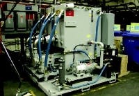
The hydraulic power unit (HPU), Figure 1, includes a 400-gal reservoir, two 100-hp electric motor-hydraulic pump units for the motion system (connected in parallel), and a manifold assembly with three filters. Two hydraulic circuits, one for motion power and the other for cooling and filtration, are independent. The systems do share a reservoir and are mounted on a single base frame. A modular design allows for transportation and handling either as a single unit or as separate systems. The motor-pump units are mounted on the base frame on vibration isolation mounts for quiet operation, as well as to prevent transmitting vibrations to the simulator.
Unlike conventional cylinders, each actuator has pressure, return, and drain lines fully integrated within the cylinder housing. This greatly reduces part count, installation time, and minimizes potential leak sources — not to mention improves the aesthetics.
Each actuator provides electronic position feedback from a magnetostrictive linear displacement transducer mounted inside. The transducers continuously monitor the position of each cylinder's piston in any simulator flight condition. The transducer, in conjunction with feedback control, guarantees each motion cue is met.
The cylinders are manufactured to CAE specifications by Honematic Corp., Boylston, Mass. Each has a bore of 4¼ in. and stroke of 60 in.
Safety and reliability
CAE's hydraulic system has safety switches for low fluid level, low pressure, and high temperature conditions. Over-running load to each actuator is accommodated by end-of-stroke cushions that prevent any damage to the mechanical hardware. In case of command loss or zero command, the actuator retracts at a controlled and safe rate until the actuator's fully retracted position is reached.
A preventive maintenance program for fluid cleanliness ensures that there is no high particle contamination, no evidence of oxidation or water, no change in viscosity, and no evidence of additive depletion. Furthermore, all filters have a differential pressure switch that triggers when filter element replacement is necessary.
Performance
The performance of the motion system follows stringent specification criteria, so the hydraulic system does not become a limiting factor in the freedom of choice of exercise by the instructor — within normal limits.
The actuator performance provides the necessary frequency response, smoothness, and stability to simulate what is expected of the aircraft. Driving the actuator with a 0.5-Hz, sinusoidal, 0.08-g peak actuator acceleration command signal generates acceleration transients to the load below 0.045 G (peak-to-peak). The system makes sure that what is commanded to the motion system is actually being driven within very low tolerances, thus matching motion cues to visual cues.
HPU operation
In startup mode, all pumps supply maximum flow at low pressure. Flow flows directly to the reservoir through a vent-relief circuit. Operating the hydraulic power supply in this mode after a long shutdown period or during a cold startup permits the fluid to warm to the recommended operating temperature.
Fluid level in the reservoir is well above the pump's suction port, so fluid at slightly above atmospheric pressure floods the pumps at the suction port. Because each pump's compensator is preset to 1500 psi, each pump supplies fluid as required to maintain the 1500-psi pressure. Flow from the discharge port of each pump passes first through a flow meter, then a check valve. The flows converge into a single cavity in the motion control manifold where three 3-µm filters are mounted in parallel. From that cavity, depending on the solenoid operated directional (pilot) valve's mode, the flow is either directed back to the reservoir (pressure vent mode) or directed to the motion base ( pressure enable mode).
Before exiting the motion control manifold, fluid passes through another non-return check valve with an adjustable flow-control (needle) valve. This check/needle valve combination controls the motion pressure line and accumulator depressurization rate. During normal operation, flow passes unrestricted through the check valve toward the motion base. For emergency shutdown and depressurization, the motion pressure line routes fluid back to reservoir through a vent circuit, and the depressurization rate (time) is adjusted by the needle valve across the check valve. The depressurization rate is set between 16 and 20 sec.
Three pressure switches, the first set at 1350 psi while rising ( pressure available), a second set at 1100 psi while decreasing (low pressure failure), and the third set at 600 psi while decreasing ( pressure line depressurized), are connected in series to the pressure line upstream of the check valve. The signals from these pressure switches are processed into the system control logic. In addition, a pressure transducer senses the motion pressure at the same point and transmits it to a cabinet display monitor. A pressure gauge installed in close proximity to the pressure switches and pressure transducer reads the pressure locally.
Return flow from the motion base to the HPU is routed through two parallel lines to reduce the maximum return fluid velocity. Before flowing into the reservoir, the flow passes through a 35-psi backpressure check valve. The return line backpressure is required to prevent return line negative pressure fluctuations. This is better achieved in conjunction with small return line accumulators at the motion base.
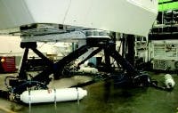
Fluid flows into the motion base through a distribution manifold, which delivers the fluid to the base corner manifolds, each equipped with 40-gal accumulators, Figure 2. The accumulators accommodate momentary peak flow demands that exceed the capability of the pumps.
Fluid then flows to each actuator, where input signals either require a flow demand or route the fluid through the return line and back to the reservoir. The return line is equipped with a check valve and a 10-gal accumulator to restrict fluid pulses, backpressure, and fluid-borne noise.
Fluid stays cool and clean
A fixed-displacement vane pump draws fluid from the reservoir through a suction line located below fluid level. After exiting the pump outlet, fluid passes through a non-return check valve, then through a 1-µm filter, and then enters a water-to-oil heat exchanger. The cooled fluid exits the heat exchanger and is directed back to reservoir through a 4-psi non-return check valve. The 4-psi check valve creates sufficient backpressure to provide flow through the motion pumps' case, for flushing and cooling during the periods that the pumps operate at full speed, with no flow, while pressure compensating. A pressure gauge is installed in the cooling system fluid supply line on the filter. In addition to the cooling pump flow, the heat exchanger cools fluid from the motion servoactuators' piston drain line, which is also directed through a non-return check valve to the heat exchanger.
Should the cooling pump or its electric motor fail, a portion of the motion return line flow would be diverted through the heat exchanger by a manually operated shut-off valve. This alternate cooling method allows continuous system operation until the failed system is repaired or replaced.
A 100-µm water filter is installed next to the heat exchanger assembly to prevent water particulate contaminants from entering the heat exchanger.
A temperature controlled adjustable water regulator valve is installed in the water outlet line between the heat exchanger and the shut-off valve. The water regulator valve senses the fluid temperature in the reservoir through a capillary, which then acts against a spring-loaded actuator poppet to open the water passage. The water regulator is manually adjusted to maintain the reservoir fluid temperature between 105° and 113°F.
Giuseppe Mallaci, P.E., is group leader, hardware engineering,for CAE. Contact him at (514) 341-2000 ext. 3621, or visit www.cae.com.
Click here to view a variety of videos from CAE.
