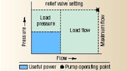
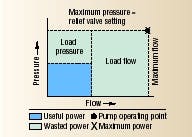
Figure 1. Pressure-flow curve of hydraulic system with fixed-displacement pump. A pump's maximum flow and pressure capability combined is known as corner power.
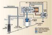
Figure 2. Schematic of a typical proportional pump pressure compensator control.
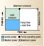
Figure 3. Pressure-flow curve of variabledisplacement hydraulic pump equipped with pressure compensation.
Figure 4. Schematic of pump two-stage compensator control.
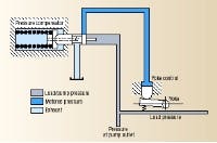
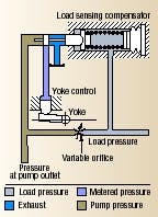
Figure 5. Schematic of proportional pump compensator that provides load-sensing capability.
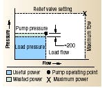
Figure 6. Pressure-flow curve of pump with load-sensing control. Note the small area of wasted power from 200-psi pilot pressure.
Pressure compensation and load sensing are terms often used to describe pump controls that improve the efficiency of pump operation. Sometimes these terms are used interchangeably, a misconception that is cleared up once you understand the differences in how the two enhancements operate.
To investigate these differences, consider a simple circuit using a fixed-displacement pump running at constant speed. This circuit is efficient only when the load demands maximum power because the pump produces constant flow whenever it is running (unless high hydraulic pressure bogs down the speed of the driving motor). A relief valve prevents excessive pressure buildup by routing high-pressure fluid to tank when the system reaches the relief setting. As Figure 1 shows, power is wasted whenever the load requires less than full flow or full pressure. The unused fluid energy produced by the pump becomes heat that must be dissipated.
Powering multiple loads
If a single pump must power multiple actuators, a proportional pressure compensator often is used. With this setup, Figure 2, a yoke spring pushes the pump's swashplate toward full displacement. When load pressure exceeds the compensator setting, force from fluid pressure acts on a compensator spool to overcome the force exerted by the spring. The spool then shifts toward the compensator-spring chamber, which routes pump output to a stroking piston to decrease pump displacement. The compensator spool returns to neutral when pump pressure matches the compensator spring setting. If a load blocks the actuators, pump flow drops to zero.
Using a variable-displacement, pressure-compensated pump rather than a fixeddisplacement pump can reduce power requirements dramatically, Figure 3. Output flow from a pressure-compensated pump varies according to a predetermined discharge pressure as sensed by an orifice in the pump's compensator. Because the compensator itself operates from pressurized fluid, the discharge pressure must be set higher — say, 200 psi higher — than the maximum load-pressure setting. Therefore, if the load-pressure setting of a pressure-compensated pump is 1100 psi, the pump will increase or decrease its displacement (and output flow) based on a 1300-psi discharge pressure.
A two-stage pressure-compensator control, Figure 4, uses pilot flow at load pressure across an orifice in the main stage compensator spool to create a pressure drop (AP) of, say, 300 psi. This pressure differential generates a force on the spool, which is opposed by force from the main spool spring. Pilot fluid flows to tank through a small relief valve. A spring chamber pressure of 4700 psi provides a compensator control setting of 5000 psi. An increase in pressure over the compensator setting shifts the main stage spool to the right, routing pump output fluid to the stroking piston, which overcomes bias piston force and reduces pump displacement to match load requirements.
Output pressure from a pressure-compensated pump can fall below the compensator setting while an actuator is moving. This does not happen because the pump is sensing the load; it happens because the pump is undersized for the application. Pressure drops because the pump cannot generate enough flow to keep up with the load. When properly sized, a pressure-compensated pump should always force enough fluid through the compensator orifice to operate the compensator.
Superior dynamics
With respect to its pressure matching function, a two-stage compensator is identical to the proportional compensator control shown in Figure 2. However, the dynamic performance of the two-stage control is superior. This becomes obvious by analyzing a transient that involves a sudden decrease in load flow demand, starting from full stroke at low pressure.
The single-stage control spool routes pressurized fluid to the stroke piston only when pump discharge pressure reaches the compensator setting. However, the main-stage spool of the two-stage control starts moving as soon as pump discharge pressure, minus spring chamber pressure, exceeds the 300-psi spring setting. Because pilot fluid flows through the orifice, and because of the flow needed to compress the fluid in the spring chamber, the spring chamber pressure lags pump discharge pressure. This causes the spool to become unbalanced and shift to the right.
Pump destroking starts before pump discharge pressure reaches the compensator setting. Note that in a system equipped with an accumulator, a two-stage compensator control provides little advantage. In excavator hydraulic systems, however, superiority of the two-stage compensator is evident: it provides system components much greater protection against pressure transients.
Load sensing: the next step
A similar control, which is becoming commonplace, is the load sensing control, sometimes called a power matching control, Figure 5. The single-stage valve is almost identical to the single-stage compensator control illustrated in Figure 2, but the spring chamber in load sensing is connected downstream of a variable orifice rather than directly to tank. The load-sensing compensator spool achieves equilibrium when the pressure drop across the variable orifice matches the 300-psi spring setting.
Any of three basic load-sensing signals control a load-sensing pump: unloaded, working, and relieving. In the unloaded mode, the lack of load pressure causes the pump to produce zero flow at bias (unload) pressure. When working, load pressure causes the pump to generate flow in relation to a set pressure drop, or bias pressure. When the system reaches maximum pressure, the pump maintains this pressure by adjusting its discharge flow.
Like the pressure-compensated pump, a load-sensing pump has a pressure-compensation control, but the control is modified to receive two pressure signals, not just one. As with pressure compensation, the load-sensing control receives a signal representing discharge pressure, but it also receives a second signal representing load pressure. This signal originates from a second orifice downstream from the first. This second orifice may be a flow-control valve immediately beyond the pump outlet, the spool opening of a directional control valve, or it may be a restriction in a fluid conductor.
Comparing these two pressure signals in the modified compensator section allows the pump to sense both load and flow. This reduces power losses even further, Figure 6. Output flow from the pump varies in relation to the differential pressure of the two orifices. Just as the pressure-compensated pump increased its discharge pressure by the amount required to run the pressure compensator, the load-and flow-sensing pump's discharge pressure typically is between 200 and 250 psi higher than actual load pressure.
Furthermore, a load-sensing pump can follow the load and flow requirements of a single circuit function or multiple simultaneous functions, relating power to maximum load pressure. This consumes the lowest possible power and generates the least heat.
Operator control
If the variable orifice is a manually operated flow-control valve, the system can operate in a loadmatched mode at the direction of an operator. When the the flowcontrol valve opens, flow increases proportionally at a pressure slightly above load pressure.
Because the control senses pressure drop, and not absolute pressure, a relief valve or other means of limiting pressure must be provided. This problem is solved by using a load-sensing/pressurelimiting control. This control functions as the load-sensing control previously described, until load pressure reaches the pressure limiter setting. At that point, the limiter portion of the compensator over-ridesthe load-sensing control to destroke the pump. Again, the prime mover must have corner power capability.
This information was excerpted from the 2004-2005 Fluid Power Handbook & Directory.
