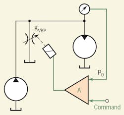
One of the justifiable objections to a two-way pressure control system is that it lacks positive shut off of the load through-flow. This is best appreciated by considering the load as a hydraulic motor, as illustrated in Figure 1. With the single bypass valve, the motor cannot be decelerated hydraulically. Instead, it depends on its shaft load to slow it down. Also, it cannot positively stop the actuator unless, again, the shaft load has some braking feature. The simple circuit can be modified slightly to overcome these limitations.
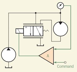
The ploy is to replace the simple two-way valve with a three-way valve. The three-way valve has two metering lands, and they are configured so that as one opens, the other closes. Therefore, to bring the motor to a stop, the valve must shift fully to one side; for maximum speed, the valve must shift completely to the other side. In the stopped position, the meter-out land is closed, blocking motor flow while the bypass land is fully opened. For maximum speed, the bypass is blocked, and the meter-out land is fully open. However, the motor's direction of rotation cannot be reversed.
Differential pressure control with fixed-displacement pumps
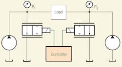
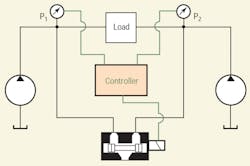
Differential pressure can be controlled using fixed displacement pumps and electrohydraulic proportional or servovalves. However, two pumps and two valves are required, as shown in Figure 2. The function is quite similar to the gauge pressure controller just discussed, and the sizing issues are very similar.
Differential pressure control does not necessarily control the gauge pressures on the two sides of the load. For example, differential pressure can be completely controlled with only one of the valves being variable. By changing only one of the valves, pressure on that side of the circuit could rise from its minimum (which is determined by the pump flow and the full open valve coefficient on that side) to any safe upper limit. Meanwhile, pressure on the opposite side would remain essentially constant at some mid-range value.
The load differential pressure can be positive or negative. It should be evident that pressure on the opposite side can also be made to rise to any safe limit while the other side remains constant. Thus, when both valves are continuously variable, the differential pressure can be controlled.
What about the gauge pressures on each side? In the example at hand, one side of the load is always at minimum while the other rises. Therefore, the maximum gauge pressure on either side is simply the minimum pressure plus the maximum desired target differential pressure on the respective side. The two gauge pressures are under a kind of control in that they are limited, even though that is not the specific aims of the feedback controller.
Coordinating valve opening and closing
A coordination that takes place between the two valves is more subtle. Coordination is accomplished through the controller: When one valve is being modulated electronically, the other valve is forced into its full open state. In other words, the controller — either by analog design or with software in a digital controller — would have to cause the two valves to behave in that prescribed manner. The specific variations in the gauge pressures depend on the specific logic that coordinates the two lands.
Other methods exist for coordinating the opening and closing of the two valve lands. However, before exploring them, note that the advantage of electronic coordination is the ease with which the relative timing in opening and closing can be adjusted.
For example, bias currents can be provided to put each land in its mid position. Command voltage, then, would create varying spool positions to control motor (load) differential pressure. This control strategy will raise the gain of the valve, thereby increasing sensitivity. Again, the gauge pressures depend on the specific method and amount of biasing and varying the two lands.
Other methods of coordination
Purely mechanical means can be used to perform the coordination function and its effects upon the two gauge pressures. Consider that a single valve controls differential pressure, as illustrated in Figure 3. The coordination is accomplished by the two variable coefficients mounted on a single spool so that as one goes up, the other goes down. In this configuration, the gauge pressure on either side will be a fairly complex function of the specific orifice geometry variation designed into the valve lands, the load resistance, and the output flows of the two individual fixeddisplacement pumps.
The advantage of this circuit are that differential pressure — and its algebraic sign — is controlled. Also, it uses fixed-displacement pumps. Lastly, there is only one proportional valve, which must cross over center. However, the valve is not zero lapped. In fact, the valve is more like an open-center valve than a closed-center one, but it has only two variable lands. This kind of valve has been referred to as a reverse three-way valve, or a flow combiner valve, which is a kind of flow divider valve. Whatever it is called, it can make a very good differential pressure control system.
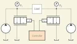
The valve in Figure 4 provides a relieving function, as both lands are open when the spool is centered. The amount of opening (under lap) in the centered position can be reduced, and doing so will stiffen the servoloop by raising the two gauge pressures. The tradeoff is a reduction in efficiency.
On the other hand, when the valve is centered, the two gauge pressures can be made as small as desired by making the valve larger. However, note that if a zerolapped valve is used, such as the one depicted in Figure 4, an external relieving function is required.
Variations on the two-pump VP control circuit
There are disadvantages to the foregoing circuit, not the least of which being that it requires two pumps. Also, some inefficiency is associated with the use of valve lands to control pressure. This is because they constantly consume full pump flow, and do so at some pressure — even if the control valve is hydraulically centered. Clearly, the valve designer's challenge is to create a valve with lands that vary with control current in a way that provides smooth, stable differential pressure variation. Moreover, the valve must not consume excessive power when in the neutral (centered) position. Can any of these disadvantages be overcome? Of course.
The double-pump can be replaced by a rotary flow divider, which is really two fixeddisplacement motors connected through a common, internal shaft. In addition, the single, main pump that supplies the flow divider need not be fixed displacement. It could be electronically variable, so that the maximum through-flow can be varied at any degree of valve shift. This also provides the possibility that if sustained periods of standby occur (the valve is centered), the main pump displacement could be backed off, reducing the power wasted during those intervals.
It should be apparent that the two-pump differential pressure control circuit makes sense only if the application requires or allows for sustained through-flow. Motors, rotary actuators, and cylinders (both single-double-rod types) are loads that make the most sense. It is more than likely that torque or force is the control target, with pressure control used for pragmatic reasons discussed earlier. Note that pressure, force, torque, actuator speed, or whatever, all are fully reversible.
Another advantage of this circuit is that it can be used for position as well as pressure control. It has several advantages over conventional four-way servo or proportional valve control. First, the valve is extremely simple, having no overlap or dead zone. However, it does not require the manufacturing precision required of zero-lapped valves. Second, because the valve is basically open center, a great deal of hydraulic damping occurs, even in systems with extremely low mechanical friction. Third, fixed-displacement pumps will work.
On the other hand, this circuit lacks inherent steady-state position loop stiffness because of the valve's open center. In addition, the ability to hold position against varying loads is not as effective as with closed-center valves.
