Many of today's hydraulic systems contain insoluble contaminants, which are too small to be trapped by filters — and too small to be detected by particle counting. This varnish formation is a serious problem that degrades system operation. Conclusive proof now exists that the root cause of tar and varnish formation is the buildup of insoluble soft contaminant oxidation byproducts.
What causes the formation of these insoluble soft contaminants? The process of oxidation is caused by a combination of water, heat, and oxygen. The heat is caused by static discharge, a process discovered several years ago that damages a filter's center core. Now, with additional study, there is solid visual proof that static discharge occurs throughout the entire hydraulic system, causing the formation of tar and varnish and reduced system performance.
Static discharge is generated through friction within the oil, and can generate sparks with temperatures greater than 10,000° C — hotter than the surface of the sun for a nanosecond. The heat generated "cooks" the oil, speeding additive decomposition and the formation of oxidation byproducts that coat tacky layers of varnish on all internal metal, rubber, and synthetic material surfaces. Over time, hard contaminant particles stick to the tacky varnish to create a sandpaper-like surface. The end result is sticky valves and reduced system performance. Left unchecked, system failure will occur.
In addition, the high acid content in varnish can cause brittleness in system seals and O-rings. Because the tacky nature of varnish can attract larger particles, seals in moving parts can be cut or otherwise damaged to the point of significantly reducing seal life.
There is good news: varnish formation can be eliminated before it causes problems. And, if you are already dealing with varnish issues, you can reverse the process back to the point of having clean oil continuously.
The culprit is heat
Hydraulic systems have four heat sources:
friction — the combination of oil against the metal surfaces in the system, as well as metal parts rubbing together, can generate temperatures between 180° and 450° C.
adiabatic compression — similar to dieseling, can generate temperatures between 600° and 900°C.
dark stream spark discharge — with no flash of light, temperatures between 5000° and 10,000° C can be generated.
full spark discharge — with flash, will generate nano-second temperatures from 10,000° to 20,000° C.
Note that spark discharge also produces metallic ions and water. Oil molecules have hydrogen, and oil contains 9.5% air, 21% of which is oxygen.
Spark discharge can occur by friction of the oil, high pressure and temperature, or pressurization of filters in a return line. Friction alone is sufficient to cause spark discharge. If your hydraulic system has the combination of high pressure and temperature, spark discharge will definitely occur.
Spark discharge in a filter
You would logically expect to see varnish form on the upstream side of filter elements. But, for years it has been observed to form on the downstream side. The reason is spark discharge that takes place between the pleated edges and grounded center core.
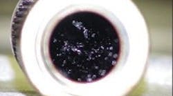
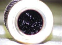
Figure 1 shows an example of spark discharge damage on a traditional filter after three months of use. The inner surface deposits are shown on the center core, looking down from the top into the grounded filter. Sheared free radicals are absorbed on the inner surface and propagate.
Spark discharges elsewhere
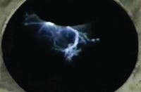
Spark discharge inside a reservoir is shown in Figure 2. The top access plate has been removed to show a 6-in. return line. The nanosecond long spark being generated without the use of a filter is 20,000° C. A video of this spark discharge test can be found at www.kleentek.com/video.asp
To eliminate the potential of oilto-air friction from a grounded surface, make sure that return oil pipes actually come down into the oil. Otherwise, a situation exists much like that of a big capacitor, where a charge builds in the air to the point of discharging and burning the oil.
Oxidation byproducts
Wherever oil touches any part of the hydraulic system, it deposits varnish. If varnish is in your reservoir, you will find it throughout the system — anywhere and everywhere the oil comes in contact with a surface. In addition to metal surfaces, varnish formation will affect seals and Orings. It does not make a difference what type of hydraulic fluid is used. Even chemical blends, such as phosphate esters, will generate varnish.
The electrostatic solution
Traditional oil cleaning has been through strainers, centrifuges, and mechanical filtration. These methods are effective in removing hard contaminants. But the only way to remove the insoluble sub-micron size soft oxidation products is through continuous electrostatic oil cleaning that is independent of contaminant size.
Because oil always seeks equilibrium, electrostatic cleaners use the oil in the system to clean the system. This balancing process draws the oxidation by-products from the system surfaces back into the oil where they are removed through a process of re-absorption.
The electrostatic contamination collection process is shown in Figure 3. Varnish, by its nature, is polar — both positive and negative. A combination of a high voltage dc plate along with a ground plate is used in the electrostatic collector. The positive polar varnish is pulled to the negative side. Negative charged particles are pulled to ground and repulsed. The sub-micron size oxidation byproducts are trapped in a cellulose collector on a continuous oil-cleaning basis.
Electrostatic oil cleaners can be an essential part of good oil maintenance. However, they should not be solely relied on because they only remove the soft contaminants that cause varnish.
Proven benefits
Continuous electrostatic oil cleaning to remove the sub-micron size soft contaminants yields several proven benefits:
• avoids unplanned system outages
• eliminates the need for costly system flushes
• significantly enhances mechanical filter, seal, and O-ringlife
• reduces oil consumption and nearly eliminates oil disposal costs, and
• is virtually maintenance free.
The use of continuous electrostatic oil cleaners will change the percentages in your favor. Instead of having to deal with the 85% of failures traced to static discharge and oxidation related problems, you will only have to be concerned with the remaining 15%.
Lewis Lucas application engineer at UAS Kleentek, Cincinnati. For more information, email [email protected] or visit www.kleentek.com.


