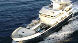
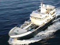
Yacht owners expect to hear a lot of things — waves crashing against the bow, wind whipping through their hair, or even music from fancy onboard sound systems. They do not, however, expect to hear their craft's hydraulic system. Many of today's top end yachts, Figure 1, now feature a central integrated hydraulic system, designed to support the stabilizer system, along with bow or stern thrusters and numerous other hydraulic loads including davits, windlasses, and capstans.
According to Ernie Romeo, chief engineer for Arcturus Marine, Rohnert Park, Calif., they see many marine systems with pressures to 4000 psi and flows to 100 gpm. A typical system will have a variety of loads, the largest requiring about 31 gpm at 3200 psi.
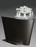
TRAC hydraulically driven digital stabilizers, from Arcturus, Figure 2, virtually eliminate roll to improve ride comfort in any sea state or wave angle. "Here, speed is the key," notes Romeo. "You must stop roll before it starts, otherwise you end up fighting the vessel's momentum as well as the forces of the sea."
These stabilizers use fins that are shaped to move through the water with minimal drag. Fins are installed in pairs, and project out around midship at an angle with its longitudinal axis running parallel to the keel. Fins are supported on a shaft that protrudes through the hull. A hydraulic actuator is controlled with a servovalve inside the hull that uses a yoke arrangement to rotate the shaft — and hence the fin. A feedback sensor is coupled to the shaft, so the fin position is known.
Sensors also measure the vessel's rate of roll and heel angle, a reference to the horizon. The sensors and valve are arranged into a servo control loop. When a correction is required to keep the boat level, fins are rotated to create lift. During lift, the higher water pressure on one side of the fin causes water on the high pressure side to tend to wrap around to the low pressure side, creating a tip vortex. Arcturus uses a winglet on the end of the fin to eliminate the tip vortex.
Fast reaction
The lightning-fast reaction time for the TRAC processor is the key to its performance. The fin angle of attack is adjusted 200 times/sec to create roll-countering lift the instant it is detected. As such, the stabilization system automatically adjusts for changes in sea-state, wave angle, and vessel speed.
But, what about reducing vessel roll while anchored, on a mooring, or while drifting? STAR (STabilization at Rest) is a feature added to the TRAC stabilizer that moves fins at the right speed at just the right moment. A three-term algorithm measures roll and controls the fin's movement to generate a smooth counter-acting energy pulse that significantly dampens roll. An electric motor-driven hydraulic pump drives the TRAC stabilizer and optional STAR stabilizer system.
No perceived noise at all
Arcturus makes it a point that careful attention is given to equipment layout and design to minimize noise and vibration. To accomplish their goal of "no perceived noise at all," Arcturus incorporates an inline Pulse-Tone hydraulic shock suppressor from Parker Hannifin Corp. directly at the hydraulic pump outlet in the engine room to stop pulsations and noise before they can travel through the hydraulic lines.
"Inline Pulse-Tone shock suppressors reduce noise associated with hydraulic systems by as much as 6 dB or more. Because every 2.7 dB represents a twofold increase or decrease in noise, the Pulse-Tone can reduce hydraulic noise by more than four times the original level," points out Mike Schubert, senior application engineer for Parker's Hydraulic Accumulator Div.
"Sometimes, these units are used when the noise level is already at what is thought to be an acceptable level," continues Schubert. In this application, the desired goal is no perceived noise at all.
"Although these pumps can be designed for low noise emission, it is still difficult to reduce the noise below the level of perception. As a result, Arcturus has designed the best of both worlds: high power density through the use of hydraulics, yet the quietness that is typically associated with electromechanical devices."
Inline shock suppressors
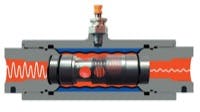
Oil flowing into a hydraulic shock suppressor, Figure 3, goes through an inner radial chamber, a compressed coil spring, and an outer radial chamber.
The inner radial chamber has ½-in. diameter holes and is surrounded by the compressed coil spring. The outer radial chamber, with its 1/32-in. holes, covers both the compressed coil spring and the inner radial chamber. The 1/32-in. diameter holes are designed to allow maximum flow while keeping a bladder — which surrounds the outer radial chamber — from extruding through them. The total radial distance between these key components is only ¼-in.
After passing through these holes, the pulsations strike a nitrogen charged rubber bladder that deflects each time it is hit by a pulsation. It is this deflection of the bladder that reduces the shock and noise.
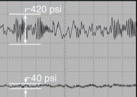
Generally, a chamber surrounding the bladder is charged with nitrogen to 50-60% of the hydraulic operating pressure. The combination of the large area of the bladder, the ability to oscillate at a high frequency, and the short distance the pulsations travel once they enter the unit explains the effectiveness of the Pulse-Tone. An example of pulsation reduction for a piston pump at 2000 and 4000 psi and 1800 rpm is shown in Figure 4.
Additional advantages
"There are significant side advantages to using an inline shock suppression system," adds Schubert. "Hydraulic pulsations and shock are reduced, so there is less component wear. This directly translates into less maintenance and longer system life."
