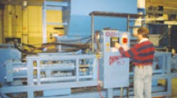
Several machines are on the market to compress metal fragments into pellets. The metal is fed into a chamber and compressed into a pellet. The problem is, most machines are single-acting. After a pellet has been made and ejected, the machine must be retracted so that the compression chamber can accept the next load of metal.
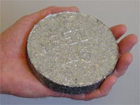
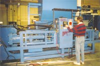
A more productive and efficient process is offered by the Model CP3 compactor, which uses a double-rod cylinder to make a pellet each time the cylinder’s piston rod extends and each time it retracts. Each pellet is compressed to about 16 its original volume. Compared to a conventional compactor, the CP3 can compact twice the amount of metal per hour while using the same amount of power. (The double-acting feature for this application is protected under US Patent 55245334.) Not only that, but the CP3 can compress different materials in its two chambers at the same time, so versatility is an added benefit.
Operation at a glance
The CP3 is controlled by a PLC, which monitors pressure and position switches and transducers to execute commands in the proper sequence with respect to time. A key component to the machine’s high throughput is its double-acting, double rod end cylinder. As one rod is extending, it compresses metal fragments. At the same time, the rod at the other end of the cylinder is retracting, opening the compression chamber for the next work cycle.
Once the rod at either end of the cylinder has retracted far enough to open the compression chamber, the PLC commands a motor to drive the respective infeed auger. After a predetermined time period, the PLC commands the auger infeed motor off and commands hydraulic valves to initiate piston rod extension.
Powered by a pair of fixed-displacement vane pumps, the piston rod extends rapidly until the metal fragments are compressed enough to cause hydraulic pressure to reach 500 psi. Once this occurs, one of the vane pumps further compresses the pellet until hydraulic pressure reaches 1200 psi.
Next, the PLC issues a command to lock the piston rod in place and then extend the rod of a die cylinder. (Once this occurs, material can be loaded into the compression chamber on the opposite side of the main cylinder.) The rod of the die cylinder directly opposes the locked rod of the main cylinder and compresses the pellet until a final hydraulic pressure is reached — up to 3500 psi.
A linear displacement transducer in the die cylinder allows the PLC to measure and record the final thickness of the pellet. After ejecting the finished pellet, the main cylinder’s rod is unlocked so it can open the chamber for the next load while simultaneously beginning the compression cycle of a new pellet on the other end of the cylinder.
The hydraulic system
The CP3 is controlled by a PLC and powered by three pumps. However, two pumps are housed in the same body. The main pump is a variable-displacement piston pump, and a two-chamber vane pump is driven off the back of the piston pump. One vane pump chamber delivers a constant 66 gpm, and the other delivers a constant 38 gpm.
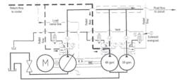
As shown in the schematic, ventable pilot-operated (PO) relief valves are plumbed into the pressure port of all three pump outlets. To limit the electric motor’s size and power drawn from the motor, different pump sections are vented to tank as the pressure rises or when lower flow rates are required during a pressing cycle.
The PLC monitors the operating pressure of the system through a pressure transducer and closes normally open solenoid valves. When these solenoid valves close, the PO relief valves also close and function as normal relief valves, limiting the maximum pressure of each pumping section. At the same time, directional valves direct fluid to the cylinders and auger motors.
This is a closed-center valve system, where all of the directional valves’ P ports are blocked when they are deenergized. The variable-displacement piston pump can destroke to deliver zero flow when its outlet flow path is blocked. However, a relief valve is used instead of allowing the pump to destroke when not needed.
This is done for two reasons. First, the piston pump takes a relatively long time to stroke from zero to full displacement. This time delay would add to the overall cycle time. Opening a relief valve is faster. Second, flow from the piston pump helps cool the hydraulic system by routing maximum oil flow through a heat exchanger.
Pump controls
Pump pressure is regulated through a load-sensing control. This type of control actually has two compensators — a load sensing compensator and a pressure compensator. The load sensing compensator limits flow to the circuit without creating excess pressure. The pressure compensator, on the other hand, limits the pressure the piston pump can develop at a certain flow. When pressure at the pump’s outlet reaches the pressure compensator setting, the pump destrokes to maintain pressure in the circuit but delivers no flow. This feature is used when the machine’s die cylinders are performing their final press cycle.
The load sensing compensator senses the pressure downstream of the flow control or directional valve and directs a pressure signal through a pilot line connecting the load being operated to the pump control. The load-sensing compensator varies the pump’s output flow by pivoting its swashplate back one direction or the other to increase or decrease displacement.
The load sensing compensator attempts to maintain pressure at the P port of the pump 200 psi higher than the pressure in the load sensing pilot line. If the working pressure of one of the augers is 1200 psi, the pump pressure at the pump’s P port will be 1400 psi. This limits the differential pressure across the flow control and, thus, limits flow delivered by the pump. Increasing the flow setting of the flow control reduces the pressure drop across the flow control. The load sensing line would sense this drop and increase pump displacement until the pressure drop across the flow control again reaches 200 psi. When multiple load sensing circuits are operating at the same time, the signal from the highest pressure circuit determines the load sensing pressure of the piston pump.
The piston pump will always try to develop 200 psi higher pressure at its P port than the pressure indicated by the load sensing line. If the load sensing feedback pressure is zero, the pressure at the P port can only be 200 psi. The working pressure of the pump will follow the pressure of the load sensing feedback pressure up to the pressure limit of the pressure compensator setting. At that point, the pump will destroke to maintain the compensation pressure.
Fixed-displacement pumps
The PLC directs flow from the vane pumps to tank by shifting the solenoid valves attached to the relief valves to tank when their flow is not required by the system. High oil flow at low pressure is required to move the center cylinder rod back and forth. When the working pressure reaches about 600 psi as the disk material compresses, the larger vane pump section is isolated from the circuit, so only the small vane pump delivers flow to the cylinders until disk compression causes fluid pressure to reach about 1200 psi. Disk precompression is then complete, and the die cylinder compresses the disk to its final density from the opposite direction.
The speed of the cylinders on the CP3 press frame is regulated by turning any of the three pumping elements on or off. As working pressure starts to rise, the PLC will start shutting off pumps to slow down the cylinder and reduce input energy requirements from the motor. When no movement from any of the motors or cylinders is required, all three pumps are vented, directing oil flow back to tank.
For more information, contact Dale Dietel at [email protected]
A time to vent
This schematic depicts the CP3 hydraulic system in its compression mode, supplied by fluid from the 38-gpm nave pump. Fluid from the variable-displacement pump flows to tank through its relief valve; fluid from the 66-gpm vane pump also flows to tank through its relief valve. This occurs because each relief valve’s respective solenoid valve is not energized, so the relief valves open at low pressure — about 50 psi. This is called venting the relief valves.
However, fluid from the 38-gpm pump flows out to the working circuit on the CP3 press assembly. This occurs because the solenoid valve has been energized, which blocks flow from the pump’s relief valve. This forces the relief valve to close, so fluid from the 38-gpm vane pump flows out to the control circuit. The check valves, downstream from each relief valve, prevent fluid in the control circuit from flowing back through a pump circuit that is being vented.
