Fluid compressibility has long been identified as a limiting factor in the time response of hydraulic circuits. An inevitable time delay occurs in changing pressure because fluid particles ( molecules) must move from one region of the circuit to another if the pressure is to change. In situations where rapid pressure change is desired, compressibility is the enemy of the circuit designer. Fluid bulk modulus often is cited as "the measure of fluid compressibility." Actually, that is quite untrue. Bulk modulus is a measure of the incompressibility of the fluid. That is, it is a measure of its stiffness, not softness. As the bulk modulus increases, the the fluid becomes less compressible.
Compressibility and capacitance
The point is, we need a measure for compressibility. It is commonly stated that circuits have hydraulic capacitance, or some amount of softness — they experience and suffer from compressibility. The first reference I saw to the usage of capacitance was by Warren Wilson in his 1950 book on hydrostatic transmissions. As an electrical engineer, I find the term appealing, because circuit analysis training applies so directly. Whereas bulk modulus is a fluid property, capacitance is a circuit property.
Hydraulic capacitance is determined by dividing the total fluid volume of a pressure-containing envelope by the fluid bulk modulus. Tubing lengths and diameters, plumbing materials (hose, steel tubing, etc.), cylinder sizes, and the like, all contribute to a circuit's capacitance. In turn, this capacitance affects the rate at which pressure can change in a given situation.
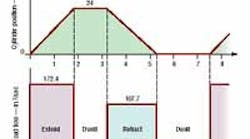
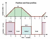
Figure 1. This single cycle of motion control and flow profiles is typical of that found in industry, where machines attempt to conduct identical operations over and over.
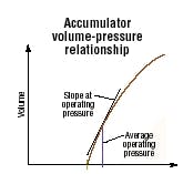
Figure 2. Hydraulic capacitance of an accumulator is the slope of a velocity-pressure curve at specific operating and precharge pressures.
Capacitance born of the fluid, its constricting material, and its constricting volume is referred to as parasitic capacitance. This term derives from the fact that, wanted or not, the capacitance comes along with the construction of the circuit, not through some deliberate act. On the other hand, deliberate capacitance can be placed in the circuit for the express purpose of preventing rapid pressure changes.
Sources of this capacitance, of course, are hydraulic accumulators, the most common of which are gas charged. Parasitic capacitance is an important subject because of its performance-limiting characteristics. But deliberate capacitance will be explored here. The capacitance concept makes writing the dynamic equations a simple process. Furthermore, parasitic and deliberate capacitances can be combined easily, a significant advantage to system modeling.
Specifically, a simple and straightforward-method exists for sizing an accumulator as an adjunct to a pressure-compensated pump. This setup is common practice in power units used in a motion control system. But how do you size an accumulator to meet a specified pressure variation limit when you know that the load flow demand changes faster than the pump's compensator can? We'll preface the answer with an example.
A practical example
What size accumulator is required to limit the peak-to-peak supply pressure variation of a system to no more than 150 psi? Assume the average supply pressure is 2000 psi, which supplies fluid to a cylinder with a 4-in. bore and 2-in. rod that is to extend 24 in. and then retract the same amount. The time to extend is 1.75 seconds, followed by a dwell of 1.44 seconds. Extension then occurs over 2.1 seconds, followed by a dwell of 2.2 seconds. Typically, this type of cycle, shown in Figure 1, would be repeated over and over again in an industrial process.
The simplified method about to be covered relies on some reasonable assumptions:
- The cycle time is sufficiently short so that adiabatic conditions exist in the accumulator's gas precharge.
- The precharge gas, nitrogen, behaves in a manner consistent with the ideal gas law.
- The pump displacement does not change as the flow demand moves from point to point.
This holds true if the change in flow demand is no more than 1/3 that of the pump's displacement slew rate. For example, if the pump slew rate is 3 gpm/sec, flow demand cannot change faster than 1 gpm/sec. Otherwise, the compensator cannot keep up with the changes in demand flow. So the accumulator helps limit pressure variations, and because pressure variations cause changes in displacement, keeping pressure variations small keeps displacement variations small.
4. The accumulator undergoes discharge-charge-discharge cycles, but the charging flow from the pump is assumed to be constant (for the reasons given above). However, the load demand and accumulator flows vary with time.
5. A real-world load flow demand wave shape usually has sloping sides — that is, with finite acceleration time. However, we will treat it as if it has vertical sides. The wave shape is approximated in Figure 1. The wave shape of the flow profile affects the exact pressure variation. However, the volume exchange between the accumulator and the cylinder as it extends, dwells, retracts, dwells, etc, has the greatest effect on dynamic pressure variation. This assumption of rectangular flow wave shape is a critical part of the simplifying process. However, it does contribute a small error in the final accumulator size calculation.
The approach to the problem is to use the pressure variation specification (150 psi maximum) and the fluid volume variation caused by the cylinder extension and retraction to calculate the hydraulic capacitance. The capacitance can then be used to calculate the accumulator volume. What is needed now, is a relationship between accumulator volume and hydraulic capacitance.
Capacitance of an accumulator
Capacitance between the pump and valve inlet port is desirable because the compressibility helps to maintain constant supply pressure, even though flow is changing. This is one reason why accumulators are incorporated into power units.
So we shall now evaluate the capacitance of a gas-over-liquid (hydropneumatic) accumulator. The capacitance of the accumulator is the slope of its pressure-volume curve, Figure 2. The derivation involves the differentiation of the equation of volume as a function of pressure, and the starting point makes use of the familiar ideal gas law.
The primary cause of capacitance in a hydropneumatic accumulator is compressibility of the gas. The behavior of the gas can be approximated with the ideal gas laws under isothermal (constant temperature) or adiabatic (no heat energy enters or leaves the system) conditions.
Most situations exhibit adiabatic conditions. We will begin under this assumption, but in reality, pure adiabatic or pure isothermal conditions never exist. However, assuming adiabatic operation produces the best estimate of system behavior.
Either of two conditions must exist for adiabatic charge and discharge. First, the accumulator envelope must be insulated to avoid internal and external temperature differences from causing appreciable energy transfer through the envelope. Second, cycle rates should be relatively high to avoid appreciable energy flow through the envelope when a difference between internal and external temperatures does exist. Because adiabatic is probably the closest approximate condition, we will proceed, next month, with that assumption.
Contact him by calling (414) 236-5350, e-mail [email protected], or visit his website at www.idaseng.com. The website describes testing, research, and design facilities and services, instructional videos, books, and software, all geared toward electrohydraulic system design. It also contains complete, unedited versions of this and previous "Motion Control" columns.


