By Jack L. Johnson, P. E.
Last month we learned that the required voltage error at 5000 psi was 0.5 V, corresponding to 500 psi. Thus, the error at an output pressure of 2500 psi would have to be less for two reasons. First, the through-flow is less at 2500 psi than at 5000 psi. Second, greater pressure drop across the control valve allows a smaller opening for the requisite through-flow. This begs the question: "Can a Type 0 regulator be converted to a Type 1 regulator so that steady state error becomes zero?" The answer: of course, by incorporating one of the variations of integral control into the electronics.
Continuing our example, if the end-to-end gain is 5000 psi of output per 5.5 V of command, then the closed loop, system calibration is 5000/5.5, or 909.09 psi/V. Thus, if we want an output of 2500 psi, then the required command voltage must be 2.75 V. This ratio works at all desired pressure levels if the transducer is essentially linear and the through-flow is laminar (linear with pressure changes). However, if through-flow is not laminar, then a non-linear calibration factor is needed — in other words, the pressure/volt ratio varies with set point.
Why use integral control?
Integral control allows us to make calculations in our heads but adds to stability problems. This makes loop tuning more difficult and increases settling time. Integral control presents another benefit, which is more subtle. Control theorists refer to it as robustness. With integral control, the system is more robust than it is without integral control.
Consider the situation where the through-flow must vary randomly. At any given moment, the flow could be anywhere between some minimum and maximum. Without integral control, a corresponding command voltage would cause the calibration factor to be a function of the amount of through flow. But integral control automatically adjusts itself, so steady-state error is driven to zero. Therefore, the output pressure/volt remains constant regardless of the through-flow.
Proportional integral control
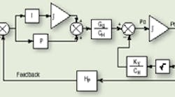
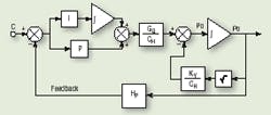
PID (proportional, integral, derivative) is a classic method of control. But its simpler cousin, PI (proportional, integral), normally will suffice and is simpler to tune. It is represented in block diagram form in Figure 1.
Note that feedback around an integrator destroys its pure integration function, but feed-forward around an integrator does not. The system of Figure 1 will produce no error in steady-state and allow us to return to a condition wherein the calibration of the pressure transducer is also the calibration of the entire feedback control loop.
If integral control is specified for a through-flow system, but no through-flow is present, the integrator is not always beneficial. Greater understanding of the control valve is required to understand how disturbances act to cause null shift in the valve and, thus, produce errors.
If integral control is used in this system, the designer must expect greater difficulty tuning the system and an increased settling time. The addition of integral control will add about 33% more time for the loop to settle out when it is tuned for minimum settling time. Increased settling time is understood by comparing it to that which would be experienced if only proportional control had been used. So if we tune for minimum settling time with proportional control only, we can expect minimum settling time to be about 1/3 longer with integral control. With step inputs, settling time cannot be made shorter.
Other load considerations
Although dead volumes with or without through-flows constitute a large part of the pressure control environments, there are others, which can be more complex. For example, pressure control often is used when the preferred control variable is force from a cylinder or torque from a motor. The logic behind this method is that if the actuator has low friction, then regulating inlet or differential pressure will result in a very nearly regulated output force or torque.
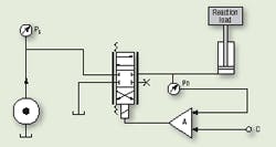
To illustrate the critical points, consider that the pressure in a cylinder has to be controlled at a commanded level, as suggested in the simplified schematic of Figure 2. The nature of the load determines if and how the pressure can be controlled. For example, if no load is applied to the cylinder, it will be impossible to control the pressure. Again, if valve control is to be used, the valve would open in an attempt to increase the pressure to the target value. However, with no load, the cylinder would extend, the valve would open more, and cylinder speed would increase — but the pressure would never rise! Clearly, a cylinder with no load is not a candidate for pressure control. Position and speed control are easily accomplished, but not pressure, nor force, for that matter.
Other kinds of loads do accommodate pressure control. Consider a load that behaves like a spring. That is, as the cylinder extends, the spring compresses, and the force needed to hold the cylinder against the compressed spring increases with cylinder extension and decreases with cylinder retraction.
Consider replacing the box labeled Reaction Load in Figure 2 with a spring that compresses as the cylinder extends. With low values of commanded pressure, cylinder extension will be slight. But higher command pressures will produce greater cylinder extension. In fact, in such a system, each pressure level results in a unique spring compression and, therefore, a unique cylinder position. It may appear to be a position control system, but it is not.
Controlling a varying load
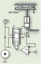
A useful example of pressure control with a cylinder against a spring load occurs very often in fatigue testing machines, suggested schematically in Figure 3. Assume we must study flexure of a truck or bus frame. In a simple configuration, the frame is anchored at or near each end, and a cylinder or two are placed at or near the center in such a way that they cause the frame to bend or flex.
Fatigue testing results from cycling the pressure up and down, changing the load on the frame, changing flexure of the frame, and evaluating the frame's ability to sustain a specific cyclic level of loading. Evidence of fatigue failure in the bends, joints, or weldments will appear if they lack the requisite fatigue strength.
Note that the frame load is the spring. As far as the cylinder is concerned, it simply sees a spring, the force of which varies with the amount of cylinder motion. It should be obvious that the desired control variable here is force.
However, pressure control is normally less expensive. Again, if the cylinder friction is small, then good force control can result. It should also be obvious that by controlling force, rather than position, the test is conducted at a specified and controlled load, not deflection.
Regarding cost, pressure control is usually less expensive and less problematic than force control in fatigue tests for at least two reasons. First is cost of transducers. Although they are probably both strain gage types, a typical pressure transducer is less expensive than a typical load cell. Second is that in fatigue testing, not only the test specimen is tested for millions of cycles, but everything in the test system is likewise cycled.
Instead of using a single cylinder applying a concentrated load at a single point, fatigue testing often is carried out with multiple cylinders in order to simulate a load that is distributed over a large area. Consider, for example, an airfoil, or wing. When in flight, wing loading is caused by differential air pressure spread more or less uniformly over the entire wing area. When multiple actuators are used, they must communicate with each other through the common load connection — the airfoil — if they are controlled as position loops. That is, as an inboard actuator moves and deflects the wing, the deflected wing pulls the outboard actuators outward, too. Therefore, the outboard actuators become part of the load for the inboard actuator. This is referred to generically as cross-talk, because one cylinder affects the action of another. In other words, one cylinder alters the load seen by another cylinder.
This is clearly not the desired situation. All actuators must impart some positive load on the airfoil at a level experienced in actual flight. The wing will be falsely loaded if it pulls any of the actuators. The outboard actuators must stay ahead of the inboard actuators, so to speak.
How is this most easily accomplished? Consider that each actuator is subjected to position control. It should be obvious that each one must travel progressively farther at the outboard positions than at the inboard positions. It would be difficult or impossible to maintain a commanded position profile for each actuator to ensure that the correct force was generated by the actuator.
Indeed, force is the desired controlled variable. It makes sense then, that force should be the measured quantity, but for reasons already given, pressure control offers some practical advantages over force control. Therefore, the final system has a multiplicity of actuators, each with a travel commensurate with its distance from the wing root and each with its own pressure level or output force level. The position of the actuator piston, then, is a dependent variable, while the load on the wing is under total control as the independent variable. Each cylinder will go to whatever position is needed to accommodate the commanded pressure or force level.
A word from the author
This animated video clearly and graphically describes the dynamic actions that take place when using electrohydraulic feedback control. You can see the command changing and immediately observe the effects on the output of a cylinder. You can even track the control valve current. And perhaps best of all, it is non-mathematical.
And what happens to the error in the servo system? You'll be able to examine that, too, and for a small fraction of the time and money I have invested in developing my career around these machines.
This video offers you the quickest and least painful way to gain valuable insights into the operation of feedback control systems as they are applied to electrohydraulic servomechanisms. Colorful motion graphics illustrate the more subtle nuances, such as saturation and timing of valve spool motion.
This instructive animation video production normally sells for $87.00, but we are offering it to readers of Hydraulics & Pneumatics until September-30, 2005 for the special discount price of only $69.00, plus $2.50 for S&H via U.S. Mail. An optional comprehensive Learning Exam is available for $43.00. But if you order the video and exam together, we'll bundle them for $100.00 and cover the cost of shipping via U.S. mail to any U.S. address. That's a savings of $30.00.
Pretty soon, everything is going to be servo controlled. Only the technically qualified will be able to compete in this exploding technical field. So order yours right away to get a running start on this growing motion control technology. Just call us toll-free at ( 877) IDAS-ENG [( 877) 432- 7364] with a Visa or Master Card, and you can start the easy way of learning about electrohydraulic feedback control servo systems. You can also send a check, money order, or purchase order to IDAS Engineering Inc.
In addition to being contributing editor for Hydraulics & Pneumatics, Jack Johnson is also president of IDAS Engineering Inc., East Troy, Wis. For more information, call (262) 642-7021; fax (262) 642-7025; or visit www.idaseng.com.
