This file type includes high resolution graphics and schematics when applicable.
Effective use of logic elements is a key to designing cost-effective circuits and is limited only by the designer’s imagination. Most experienced hydraulic circuit designers know and understand the many ways to apply logic elements. Logic elements, often called differential sensing valves, are pressure control devices. Like directional control valves, a spring bias holds the spool in one position (open or closed), and it is shifted by hydraulic pressure. Unlike directional control valves, logic elements are modulating devices (not on/off) that maintain a pressure differential. By themselves, logic elements are building blocks for many circuits.
Two new components in the logic element arsenal are normally closed, vent-to-open type of logic elements (such as Comatrol’s HLE10-CVO and its family) and proportional relief valves (like the HPRV08-DAC and its family).
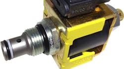
Proportional pressure relief valves (PRVs) are two-way valves that provide a relief pressure as a function of electric current. Both normally open (increasing pressure with increasing current), and normally closed (decreasing pressure with increasing current) are available. Considering the growing potential of proportional control hydraulic fan drives, we’ll use a normally closed design for fan speed control as an example.
Electrohydraulic fan application
Normally closed proportional relief valves are available in direct-acting and pilot-operated designs. A direct-acting, normally closed proportional relief valve is used for low-flow applications, like piloting a logic element. For high flow applications up to 180 lpm, internally pilot-operated cartridges are available. If the flow or pressure requirements exceed that of the internally pilot-operated valves, then combining the direct-acting PRV with the proper logic element is the next logical step.
Common applications for normally closed proportional relief valves are electroproportional control of system relief pressure or a remote pressure compensator control for open circuit piston pumps, but where system requirements dictate full pressure with no electrical signal. Most fan drive systems require the fail-safe mode (no electrical current) to provide full fan speed, which makes normally closed PRVs ideal.
Schematic examples
The example schematics show three different solutions to provide proportional speed control to a fan motor. The first two are combining a spool type, normally closed, vent-to-open logic element with a direct-acting electroproportional relief valve to create a proportional relief function. The logic element size and pressure are selected to match the system requirements. The third schematic shows the single valve advantage of the pilot-operated version (smaller size and less space needed), but is limited to flow of 180 lpm pressure to 210 bar).
The first schematic is the high flow example. If the system requires up to 380 lpm and 210 bar, then select the proper the logic element to match the capacity, such as Comatrol’s CP703-2 in combination with a PRV08-DAC. For higher pressures (middle schematic), an HLE10-CVO with HPRV08-DAC will accommodate up to 350 bar and 100 lpm. The third schematic is for flows to 180 lpm when pressure to 210 bar is needed In this case, a single pilot-operated proportional relief cartridge valve (PRV10-POC or PRV12-POC) will do the job.
This discussion was provided by Darren Magner, Director of Marketing & Product Development, Comatrol, Easly, S.C. For more information, call (864) 644-0055, email [email protected], or visit www.comatrol.com.
This file type includes high resolution graphics and schematics when applicable.


