Hydraulicspneumatics 932 Troubleshooting 1 P

Production boost causes seal leak

Dec. 16, 2013
An original-equipment manufacturer of custom automation equipment for the food-processing industry built a large pallet-transfer system to shuttle bins of poultry from a defeathering line to a final processing line. The poultry was placed into bins, 10 at a time, and the bins were stacked 10 high. The 10-high pallet-transfer system consisted of a floor-mounted rack-and-pinion drive system with a gerotor motor driving the pinion to move the pallets. The pallets were then shuttled to one of three locations to be off-loaded for final processing.

An original-equipment manufacturer of custom automation equipment for the food-processing industry built a large pallet-transfer system to shuttle bins of poultry from a defeathering line to a final processing line. The poultry was placed into bins, 10 at a time, and the bins were stacked 10 high. The 10-high pallet-transfer system consisted of a floor-mounted rack-and-pinion drive system with a gerotor motor driving the pinion to move the pallets. The pallets were then shuttled to one of three locations to be off-loaded for final processing.

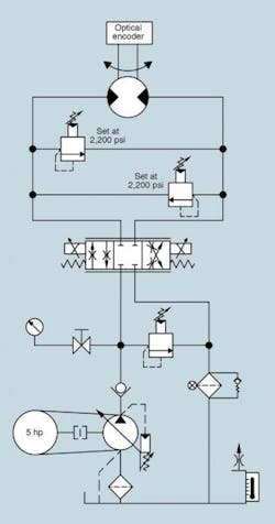
An optical encoder provided position feedback to the machine’s motion controller. The motion controller commanded an electrohydraulic proportional valve to drive the hydraulic motor’s motion accurately — to within ±½ in., in front of the correct off-loading point.

The OEM overcame the normal struggle of meeting the cycle time to provide smooth acceleration, deceleration, and positioning of the pallets. The system was tested on the OEM’s shop floor, then installed and commissioned at the poultry plant. Several months of smooth poultry operation ensued.

As usual, a call came in for increased cycle time and higher throughput. The bins were modified to accept 15 poultry bodies, and the original pressures on the system were raised to accommodate the 50% increase in load. The system pressure was raised to 1,800 psi and the cross-port reliefs to 2,200 psi. After a couple weeks, the shaft seal on the motor developed a leak. The motor, rated for 2,500 psi, was replaced. However, the new motor also developed a shaft seal leak in short order.

The motors were disassembled, but technicians found no indication of any internal damage. In fact, the motor manufacturer said they looked brand new and that internal components met
factory-new tolerances. With the rack-and-pinion design, side loading seemed to be the only possible cause for the leakage, so an overhung load adapter was installed to eliminate any side load being transmitted to the hydraulic motor’s shaft. This did nothing except allow the leakage to collect between the adapter and motor.

What do think was the problem?

Click here for solution to problem

Solution to Production Boost Causes Seal Leak:

Gerotor style motors generally do not use an external case drain for pressures lower than 1,500 psi or in non-shock loaded applications. otherwise the shaft seals experience short life. CFC's Jon Rhodes had the maintenance crew connect a case drain line from pump to tank, which solved the problem.

We always use a case drain where ever we can, regardless of the operating pressure. Shaft seal leakage is the major reason why gerotor motors are removed from service. One manufacturer claims that installing a case drain on its motors virtually eliminates shaft seal leaks. Case drains are also great to determine if a motor is worn internally by measuring leakage with the motor running at full load.
About the Author

Robert Sheaf | President

Robert J. Sheaf Jr., is the founder and president of CFC Insustrial Training, formerly Certified Fluid Consultants, part of CFC-Solar Inc. CFC-Solar provides technical training, consulting, and field services to any industry using fluid power technology. 

Continue Reading

Motor leakage variations

Oct. 18, 2006
affect low-speed performance

The Impacts of Electrification on Fluid Power Systems

May 15, 2023
Electrification presents challenges as well as opportunities to re-evaluate and improve upon the design of hydraulics and pneumatics.

Sponsored Recommendations

7 Key Considerations for Selecting a Medical Pump

Feb. 6, 2024
Newcomers to medical device design may think pressure and flow rate are sufficient parameters whenselecting a pump. While this may be true in some industrial applications, medical...

How Variable Volume Pumps Work

Feb. 6, 2024
Variable volume pumps, also known as precision dispense pumps, are a positive displacement pump that operates by retracting a piston to aspirate a fluid and then extending the...

What is a Check Valve and How Does it Work?

Feb. 6, 2024
Acheck valve, a non-return or one-way valve, is a mechanical device that allows a gas or liquid to flow freely in one direction while preventing reverse flow in the opposite ...

The Difference Between Calibrated Orifices and Holes

Feb. 6, 2024
Engineers tasked with managing fluid flow talk about both holes and calibrated orifices, but they are two distinct entities. A hole can be any opening, but a calibrated orifice...